EasyManua.ls Logo

York ZE Series User Manual

York ZE Series
78 pages
To Next Page IconTo Next Page
Page #1 background imageLoading...
Page #1 background image
R-410A
ZE SERIES
3 - 6 Ton
60 Hertz
5742637-YIM-D-0620
TABLE OF CONTENTS
General . . . . . . . . . . . . . . . . . . . . . . . . . . . . . . . . . . . . . . . . . . . . . 2
Installation . . . . . . . . . . . . . . . . . . . . . . . . . . . . . . . . . . . . . . . . . . . 5
Installation Safety Information . . . . . . . . . . . . . . . . . . . . . . . . . . 5
Limitations . . . . . . . . . . . . . . . . . . . . . . . . . . . . . . . . . . . . . . . . . 5
Location . . . . . . . . . . . . . . . . . . . . . . . . . . . . . . . . . . . . . . . . . . . 7
Rigging And Handling . . . . . . . . . . . . . . . . . . . . . . . . . . . . . . . . 7
Ductwork . . . . . . . . . . . . . . . . . . . . . . . . . . . . . . . . . . . . . . . . . 12
Condensate Drain . . . . . . . . . . . . . . . . . . . . . . . . . . . . . . . . . . 12
Compressors . . . . . . . . . . . . . . . . . . . . . . . . . . . . . . . . . . . . . . 12
Filters . . . . . . . . . . . . . . . . . . . . . . . . . . . . . . . . . . . . . . . . . . . . 13
Power And Control Wiring . . . . . . . . . . . . . . . . . . . . . . . . . . . . 13
Typical Field Power and Control Wiring . . . . . . . . . . . . . . . . . . . . 15
Typical Power Wiring . . . . . . . . . . . . . . . . . . . . . . . . . . . . . . . . 15
Typical Cool/Heat Control Wiring (Simplicity Lite ZE036-060). 15
Typical Cool/Heat Control Wiring (Smart Equipment™ ZE036-
072) . . . . . . . . . . . . . . . . . . . . . . . . . . . . . . . . . . . . . . . . . . . . . 16
Field Installed Electric Heat . . . . . . . . . . . . . . . . . . . . . . . . . . . 32
Options/Accessories . . . . . . . . . . . . . . . . . . . . . . . . . . . . . . . . 35
RRS Economizer Interface Overview . . . . . . . . . . . . . . . . . . . 35
Smart Equipment™ Economizer Sequences. . . . . . . . . . . . . .36
Dry Bulb Changeover . . . . . . . . . . . . . . . . . . . . . . . . . . . . . . . 36
Single Enthalpy Changeover . . . . . . . . . . . . . . . . . . . . . . . . . . 36
Dual Enthalpy Changeover . . . . . . . . . . . . . . . . . . . . . . . . . . . 36
Auto . . . . . . . . . . . . . . . . . . . . . . . . . . . . . . . . . . . . . . . . . . . . . 36
Free Cooling Operation . . . . . . . . . . . . . . . . . . . . . . . . . . . . . . 36
Power Exhaust . . . . . . . . . . . . . . . . . . . . . . . . . . . . . . . . . . . . 37
Operation. . . . . . . . . . . . . . . . . . . . . . . . . . . . . . . . . . . . . . . . . 37
Checking Supply Air CFM . . . . . . . . . . . . . . . . . . . . . . . . . . . . 49
Operation . . . . . . . . . . . . . . . . . . . . . . . . . . . . . . . . . . . . . . . . . . . 50
Cooling Sequence Of Operation . . . . . . . . . . . . . . . . . . . . . . . 50
No Outdoor Air Options . . . . . . . . . . . . . . . . . . . . . . . . . . . . 50
Cooling Operation Errors . . . . . . . . . . . . . . . . . . . . . . . . . . . 51
Field Installed Electric Heating Sequence Of Operations . . . . 52
Electric Heat Operation Errors . . . . . . . . . . . . . . . . . . . . . . . 52
Gas Heating Sequence Of Operations . . . . . . . . . . . . . . . . . . 53
Gas Heat Operation Errors . . . . . . . . . . . . . . . . . . . . . . . . . . . 53
Flash Codes or Error Messages . . . . . . . . . . . . . . . . . . . . . . . 54
Resets . . . . . . . . . . . . . . . . . . . . . . . . . . . . . . . . . . . . . . . . . . . 54
Heat Anticipator Setpoints . . . . . . . . . . . . . . . . . . . . . . . . . . . . 54
Start-up (Cooling) . . . . . . . . . . . . . . . . . . . . . . . . . . . . . . . . . . . . 54
Start-up (Gas Heat) . . . . . . . . . . . . . . . . . . . . . . . . . . . . . . . . . . . 55
Checking Gas Input . . . . . . . . . . . . . . . . . . . . . . . . . . . . . . . . . . . 56
Start Up For Units Equipped for FER. . . . . . . . . . . . . . . . . . . . . . 57
Direct Drive . . . . . . . . . . . . . . . . . . . . . . . . . . . . . . . . . . . . . . . 57
Belt Drive . . . . . . . . . . . . . . . . . . . . . . . . . . . . . . . . . . . . . . . . . 57
Troubleshooting (Simplicity Lite Only) . . . . . . . . . . . . . . . . . . . . . 58
Smart Equipment™ Control Board Navigation Components . . . . 66
Start-Up Sheet . . . . . . . . . . . . . . . . . . . . . . . . . . . . . . . . . . . . . . . 73
LIST OF TABLES
1 ZE036-072 Unit Limitations . . . . . . . . . . . . . . . . . . . . . . . . . . . 6
2 ZE036-072 . . . . . . . . . . . . . . . . . . . . . . . . . . . . . . . . . . . . . . . . 8
3 ZE036-072 Unit Accessory Weights . . . . . . . . . . . . . . . . . . . . 8
4 ZE036-072 Unit Clearances . . . . . . . . . . . . . . . . . . . . . . . . . 10
5 ZE036-072 Utilities Entry . . . . . . . . . . . . . . . . . . . . . . . . . . . . 11
6 Control Wire Sizes . . . . . . . . . . . . . . . . . . . . . . . . . . . . . . . . . 14
7 Electrical Data . . . . . . . . . . . . . . . . . . . . . . . . . . . . . . . . . . . . 17
8 Electrical data: single-phase gas heat, belt drive . . . . . . . . . 29
9 ZE036-072 Physical Data . . . . . . . . . . . . . . . . . . . . . . . . . . . 30
10 Electric Heat Minimum Supply Air . . . . . . . . . . . . . . . . . . . . . 32
11 Gas Heat Application Data . . . . . . . . . . . . . . . . . . . . . . . . . . 32
12 Gas Pipe Sizing - Capacity of Pipe . . . . . . . . . . . . . . . . . . . . 33
13 Smart Equipment™ Economizer Board Details . . . . . . . . . . 38
14 Altitude/Temperature Correction Factors . . . . . . . . . . . . . . . 42
15 ZE Blower Performance Side Duct . . . . . . . . . . . . . . . . . . . . 45
16 ZE Blower Performance Bottom Duct . . . . . . . . . . . . . . . . . . 46
17 Belt Drive RPM Selection . . . . . . . . . . . . . . . . . . . . . . . . . . . 48
18 Indoor Blower Specifications (Belt Drive) . . . . . . . . . . . . . . . 48
19 Power Exhaust Specifications. . . . . . . . . . . . . . . . . . . . . . . . 48
20 Additional Static Resistance . . . . . . . . . . . . . . . . . . . . . . . . . 49
21 Electric Heat Limit Setting . . . . . . . . . . . . . . . . . . . . . . . . . . . 52
22 Electric Heat Anticipator Setpoints . . . . . . . . . . . . . . . . . . . . 53
23 Single Stage Gas Heat Limit Control Setting . . . . . . . . . . . . 54
24 Gas Heat Anticipator Setpoints . . . . . . . . . . . . . . . . . . . . . . . 54
25 Gas Rate-Cubit Feet per Hour . . . . . . . . . . . . . . . . . . . . . . . 56
26 Fan setup commands . . . . . . . . . . . . . . . . . . . . . . . . . . . . . . 57
27 ZE036 (3.0 Ton) Operating Pressures . . . . . . . . . . . . . . . . . 60
28 ZE048 (4.0 Ton) Operating Pressures . . . . . . . . . . . . . . . . . 60
29 ZE060 (5.0 Ton) Operating Pressures . . . . . . . . . . . . . . . . . 61
30 ZE072 (6.0 Ton) Operating Pressures . . . . . . . . . . . . . . . . . 61
31 Simplicity Lite Unit Control Board Flash Codes . . . . . . . . . . 66
32 Ignition Control Board Flash Codes . . . . . . . . . . . . . . . . . . . 66
33 Smart Equipment™ UCB Details . . . . . . . . . . . . . . . . . . . . . 67
34 Cable for FC Buses and SA Buses in Order of Preference . 72
LIST OF FIGURES
1 ZE036-072 Component Location . . . . . . . . . . . . . . . . . . . . . . 6
2 Unit 4 Point Load Weight . . . . . . . . . . . . . . . . . . . . . . . . . . . . 8
3 Unit 6 Point Load Weight . . . . . . . . . . . . . . . . . . . . . . . . . . . . 8
4 Center of Gravity . . . . . . . . . . . . . . . . . . . . . . . . . . . . . . . . . . 8
5 ZE036-072 Cooling Only Front View Physical Dimensions . . 9
6 ZE036-072 Cooling Only/Gas Heat Front View Physical
Dimensions . . . . . . . . . . . . . . . . . . . . . . . . . . . . . . . . . . . . . . . 9
7 ZE036-072 Fixed Outdoor Air Motorized Damper Rain Hood
Physical Dimensions . . . . . . . . . . . . . . . . . . . . . . . . . . . . . . 10
8 ZE036-072 Disconnect Location . . . . . . . . . . . . . . . . . . . . . 10
9 ZE036-072 Unit Side Duct Openings . . . . . . . . . . . . . . . . . . 11
10 ZE036-072 Roof Curb . . . . . . . . . . . . . . . . . . . . . . . . . . . . . 11
11 Condensate Drain . . . . . . . . . . . . . . . . . . . . . . . . . . . . . . . . . 12
12 Compressor Restraining Bracket . . . . . . . . . . . . . . . . . . . . . 13
13 Typical Field Power and Simplicity Lite Control Wiring . . . .15
14 Typical Smart Equipment™ Control Wiring . . . . . . . . . . . . . 16
15 Side Entry Gas Piping . . . . . . . . . . . . . . . . . . . . . . . . . . . . . 33
16 Bottom Entry Gas Piping . . . . . . . . . . . . . . . . . . . . . . . . . . . 33
17 Vent And Combustion Air Hood . . . . . . . . . . . . . . . . . . . . . . 35
18 RRS Economizer LCD and Keypad Layout. . . . . . . . . . . . . 35
19 SE-ECO1001-0 Economizer Controller . . . . . . . . . . . . . . . . 38
20 Belt Adjustment . . . . . . . . . . . . . . . . . . . . . . . . . . . . . . . . . . 42
21 Altitude/Temperature Correction Factors . . . . . . . . . . . . . . . 43
22 Pressure Drop Across Coil . . . . . . . . . . . . . . . . . . . . . . . . . . 49
23 Gas Valve Piping . . . . . . . . . . . . . . . . . . . . . . . . . . . . . . . . . 53
24 Typical Single Stage Gas Valves . . . . . . . . . . . . . . . . . . . . . 55
25 Proper Flame Adjustment . . . . . . . . . . . . . . . . . . . . . . . . . . 56
26 Typical Flame Appearance . . . . . . . . . . . . . . . . . . . . . . . . . 56
27 Simplicity Lite Control Board . . . . . . . . . . . . . . . . . . . . . . . . 66
28 Smart Equipment™ Unit Control Board . . . . . . . . . . . . . . . . 67

Table of Contents

Other manuals for York ZE Series

Question and Answer IconNeed help?

Do you have a question about the York ZE Series and is the answer not in the manual?

York ZE Series Specifications

General IconGeneral
RefrigerantR-410A
Indoor Unit Dimensions (HxWxD)Varies by model
Outdoor Unit Dimensions (HxWxD)Varies by model
Indoor Unit WeightVaries by model
Outdoor Unit WeightVaries by model
Power Supply208/230V, 1-phase, 60Hz

Summary

General

Safety Considerations and Signal Words

Alerts and signal words for potential injury and property damage. Pay attention to DANGER, WARNING, CAUTION.

Installation Limitations and Code Compliance

Installation must comply with codes and manufacturer's instructions. Use R-410A compatible servicing equipment.

Reference

Technical Guide Reference

Reference to technical guide ZE036-072, 5190086 for additional information.

General Installation Reference

Reference to general installation ZE036-072, 5742637 for installation procedures.

Renewal Parts Information

Contact local York parts distribution center for authorized replacement parts.

CSA Approvals

Design certified by CSA for cooling only, outdoor installation, combustible material, and natural gas use.

Nomenclature

Model Nomenclature: Product Category

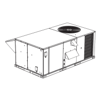
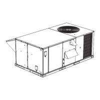
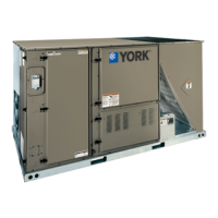
Defines the product type, such as Package A/C.

Model Nomenclature: Product Identifier

Identifies the product's efficiency rating, e.g., Standard Efficiency.

Model Nomenclature: Cooling Capacity

Specifies the unit's cooling capacity in tons (e.g., 3 Ton, 4 Ton).

Model Nomenclature: Heat Type

Indicates if the unit is cooling only or has gas heat options.

Model Nomenclature: Heat Capacity

Specifies the gas heat input in MBH for different unit sizes.

Model Nomenclature: Refrigeration

Details the type of refrigeration system, e.g., Standard Refrigeration or ECC.

Model Nomenclature: Blower Option

Specifies the blower type, such as Direct Drive or Standard Static.

Model Nomenclature: Voltage

Indicates the electrical voltage options for the unit (e.g., 208/230V, 460V).

Model Nomenclature: Controls Option

Details the control system options like Stand Alone Smart Equipment or Simplicity Lite.

Model Nomenclature: Outdoor Air Option

Specifies economizer types, including No Economizer or Economizer with Barometric RLF.

Model Nomenclature: Sensors

Details the sensor options like Phase Monitor, Dirty Filter Switch, or Smoke Detectors.

Model Nomenclature: Service Options

Indicates service options such as Disconnect Switch or Powered Convenience Outlet.

Installation

Installation Safety Information

Read instructions before installation. Ensure availability to consumer. Test for gas leaks safely.

Installation Limitations

Install according to NEC, NFPA, CSA codes, and local codes. Use R-410A compatible equipment.

Location

Rigging and Handling Procedures

Exercise care when moving. Use spreader bars. Protect coils from damage.

Required Clearances for Installation

Maintain required clearances for operation and service per codes. Avoid obstructing air outlets.

Ductwork

Condensate Drain Plumbing

Plumbing must conform to local codes. Use a sealing compound and trap the drain line.

Compressors

Compressor Protection Features

Compressors have inherent protection. Anti-Short Cycle Delay (ASCD) minimizes wear and damage.

Filter Installation and Maintenance

Filters must be kept clean or replaced. Dirty filters reduce capacity and can cause shutdown.

Power and Control Wiring Requirements

Field wiring must conform to NEC, CEC, and local codes. Use copper conductors and separate branch circuits.

Typical Field Power and Control Wiring

Typical Power Wiring Diagram

Connects contactor, disconnect, and power supply. Size disconnect, protection, and wiring per electrical data tables.

Simplicity Lite Control Wiring Diagram

Illustrates thermostat wiring to control terminal block for Simplicity Lite units.

Typical Cool/Heat Control Wiring (Smart Equipment™™ ZE036-072)

Smart Equipment: R~Occ Jumper

Jumper wire between R and OCC terminals. Must be removed for thermostat/EMS control of Occupied mode.

Field Installed Electric Heat

Optional Gas Heat Details

Gas-fired heaters use tubular heat exchangers with spark ignition. Shipped for natural gas, convertible to LP.

Gas Piping

Gas Supply Line Connection

Route gas line within space, exit through basepan. Refer to figures for piping arrangements. Use appropriate fittings.

LP Gas Unit, Tank, and Piping Requirements

Vent and Combustion Air Hood Installation

Install vent and combustion air hoods for proper unit function. Fasten to access panel with provided screws.

RRS Economizer Interface Overview

Economizer User Interface Overview

LCD display and 4-button keypad on economizer module for navigation and settings.

Economizer Keypad Functions

Four navigation buttons for scrolling menus, selecting items, and changing parameters.

Navigating Economizer Menus

Instructions on using enter, scroll, and escape buttons for menu navigation and parameter changes.

Options/Accessories

Electric Heat Accessory Details

Field-installed accessories. Mount in heat compartment. Fused and single point power.

Economizer/Damper/Rain Hood Installation

Instructions for assembling economizer rain hood. Dampers, actuator, and sensors are factory mounted.

Power Exhaust/Relief Damper/Rain Hood Installation

Instructions for power exhaust/barometric relief damper and rain hood. Field assembled.

Smart Equipment™™ Economizer Sequences

Menu Structure

Top level menus include STATUS, ALARMS, SUMMARY, COMMISSION, CONTROLLER SETTINGS, UPDATE, DETAILS, SELF TEST, VIEW RESULTS.

Economizer Minimum Position Setting

Set economizer minimum position during occupied mode when outside air is not suitable for free cooling.

Free Cooling Operation Modes

Four types of free cooling: Dry Bulb, Single Enthalpy, Dual Enthalpy, and Auto.

Free Cooling: Dry Bulb Changeover

Free cooling is suitable if outside air temp is 1°F below OAT Enable Setpoint and 1°F below Return Air Temp.

Free Cooling: Single Enthalpy Changeover

Free cooling if outside air enthalpy is at least 1 BTU/lb below setpoint and temp is within RAT + 9°F.

Free Cooling: Dual Enthalpy Changeover

Free cooling if outside air enthalpy is lower than return by 1 BTU/lb AND temp is within RAT + 9°F.

Free Cooling: Auto Mode

Control determines free cooling type based on available sensors (dry bulb, enthalpy, humidity).

Power Exhaust

Free Cooling Operational Details

First stage cooling is free cooling. Dampers modulate to control supply air temp to economizer setpoint.

Power Exhaust Control Setpoints

Includes Economizer Enable, Power Exhaust Enable, Modulating Power Exhaust, and Building Pressure Sensor settings.

Power Exhaust Control Outputs

2-10 VDC from ECON for actuator, 24 VAC from EX-FAN for exhaust fan.

Economizer Board: Analog Inputs

Economizer Board: Status LEDs

POWER (green) indicates 24 VAC presence. FAULT (red) indicates errors. SA BUS (green) indicates communication.

Economizer Board: SA BUS Connections

Connections for SA BUS power and communication circuits to UCB and other devices.

Economizer Board: Analog Outputs

Economizer Board: Binary Outputs

24 VAC hot outputs for actuators and fans. Common connections.

Economizer Board: Analog Input Terminals

Economizer Board: Binary Inputs

Inputs for PURGE dry contact and power exhaust VFD fault contact.

Indoor Air Quality (IAQ) Sensor

Motor Phasing Checks

Check motor rotation. Swap wires if rotation is incorrect.

Belt Tension Adjustment

Procedure for adjusting belt tension using nuts and sheave gauges.

Altitude/Temperature Corrections for CFM, Static Pressure, BHP

Using Altitude/Temperature Correction Factors

Examples demonstrate using correction factors for CFM, static pressure, and BHP at different altitudes.

Drive Selection

Drive Selection Example

Example of selecting blower speed and BHP based on CFM and static pressure data.

Checking Supply Air CFM Procedure

Operation

Cooling Sequence of Operation

Describes how the unit operates during cooling, including compressor and blower control.

Blower Operation: Continuous Mode

Supply air blower operates continuously when thermostat fan switch is set to 'ON'.

Blower Operation: Intermittent Mode

Blower operates with cooling/heating requests, with minimum run/off delays.

Operation: No Outdoor Air Options

Unit operates compressor and condenser fan when thermostat calls for cooling.

Economizer Operation: Single Enthalpy/Dry Bulb

Controls dampers based on enthalpy/dry bulb setpoints; energizes compressor or fan.

Economizer Operation: Dual Enthalpy

Chooses between outdoor/return air with lowest enthalpy for efficiency.

Economizer Operation with Power Exhaust

Unit operates with economizer and power exhaust. Second stage cooling is disabled when power exhaust is active.

Outdoor Air Damper Operation

Motorized damper opens to set position when R to G circuit is complete, returns fully closed when opened.

Cooling Operation Errors

Cooling Error: High-Pressure Limit Switch

Opens to de-energize compressor, initiates ASCD, stops condenser fan. Locks out on multiple trips.

Cooling Error: Low-Pressure Limit Switch

Monitors low-pressure switch. De-energizes compressor, initiates ASCD on openings. Locks out on multiple trips.

Cooling Error: Freezestat (Simplicity Lite)

Opens if evaporator coil temperature is too low, de-energizing compressor. Locks out on multiple trips.

Cooling Error: Evaporator Low Limit (Smart Equipment)

Detects temp below 26°F, de-energizing compressor. Locks out on multiple trips.

Low Ambient Cooling (Simplicity Lite)

Operates compressors in 10 min on/5 min off cycle below 45°F to defrost indoor coil.

Low Ambient Cooling (Smart Equipment)

Operates compressors in 10 min on/5 min off cycle below 45°F OAT to defrost indoor coil.

Cooling System Safety Controls Monitoring

UCB monitors suction freezestat, high/low pressure switches, and evaporator low limit sensor.

Electric Heat Operation Errors

Electric Heat Error: Temperature Limit

UCB senses zero volts from high temp limit, energizes blower. Monitors limit at all times.

Electric Heat Sequence: Single-Stage

Sequencer/contactor energizes. UCB energizes blower after fan on delay for heating.

Electric Heat Sequence: Two-Stage

Second sequencer/contactor energizes for two-stage heat. UCB energizes blower after fan on delay.

Gas Heating Sequence of Operations

Gas Heating Sequence of Operations

Controls pilot ignition, gas valves, draft motor, and safety monitoring.

Gas Heat Operation Errors

ICB monitors flame sense, centrifugal, primary limit, roll out switches. Closes valves and flashes code on fault.

Gas Heat Temperature Limits

Primary limit senses heat exchanger temp. Opens on high temp, closing gas valve, energizing blower.

Flash Codes or Error Messages

Resets

Electric Heat Anticipator Setpoints

Gas Valve Operation

Centrifugal Switch Function

Integral to draft motor. Closes at speed increase, opens at decrease. ICB checks for open state.

Roll-out Switch Safety

Protects furnace from excessive heat in burner area. Opens on excessive heat, requiring manual reset.

Pilot Flame Lockout Condition

ICB counts flame losses. Locks out furnace for 5 mins after >16 losses in one call. Retries after 5 mins.

Flame Sense Circuit Failure

Detects hardware failure in flame sense circuit. Shuts off outputs, enters hard lockout. Requires power cycle to recover.

Start-up (Gas Heat)

Gas Heat Start-up: Pre-start Checklist

Check gas type, vent/combustion hoods. Verify electrical power. Set thermostat to off.

Gas Heat Start-up: Operating Instructions

Turn on power. Set thermostat lower than room temp. Compressor energizes after time delay.

Gas Heat: Lighting Pilot and Main Burners

Turn off power. Turn gas valve off. Turn on electric power. Set thermostat to desired temp.

Gas Heat Start-up: Post-Start Checklist

Check gas leaks, manifold pressure, supply gas pressure. Ensure safe operation.

High-Fire Gas Flow Adjustment

Pilot Checkout Procedure

Pilot flame should envelope flame sensor. Adjust pilot flame clearance. Ensure controls function properly.

Burner Service Instructions

Close gas valve and shut off power. Remove manifold-burner assembly for service. Ensure burners are level.

Burner Air Shutter Adjustment

Adjust burner shutters to avoid yellow flame in heat exchanger tubes.

Checking Gas Input Procedure

Measure time for meter dial revolution to calculate gas consumed per hour. Compare to furnace rating.

Temperature Rise Adjustment

Start Up For Units Equipped for FER

FER Start-up: Direct Drive Units

Units have three leads for motor speeds. Adjust leads for specific airflow and static requirements.

FER Start-up: Belt Drive Units

Units use VFD for speeds. Adjust pulley for airflow changes. Adjust factory default speed settings if needed.

Adjusting Fan Speed Percentages

Use joystick to select Details, Fan, Setup. Adjust fan speed commands for specific applications.

Troubleshooting (Simplicity Lite Only)

Troubleshooting: Blower Not Energizing with Compressor

Troubleshoots blower not energizing when compressors are on. Checks thermostat, wiring, contactor, and motor.

Troubleshooting: Compressor Not Energizing with Blower

Troubleshoots compressor not energizing. Checks economizer blades, wiring, contactor, and compressor.

Troubleshooting: Compressor Voltage Checks and Lockouts

Troubleshooting: UCB Lockout and Economizer Wiring

Checks for UCB compressor lockout, ASCD, or economizer wiring issues.

Gas Heat Troubleshooting Guide

Gas Heat Troubleshooting: Flash Code Analysis

Power unit, check ICB LED. Verify wiring, control voltage, circuit breakers, and connectors.

Gas Heat Troubleshooting: Ignition Control Board

Troubleshoot ICB for pilot ignition, gas valve operation, safety monitoring. Check for heartbeat LED.

Gas Heat Troubleshooting: Centrifugal Switch

Check for fault codes related to centrifugal switch. Inspect draft motor, wheel, and wiring.

Gas Heat Troubleshooting: Primary or Aux Temperature Limit

Gas Heat Troubleshooting: Roll-out Switch

Common causes for roll-out switch opening: blocked flue, loose blower wheel, incorrect temp rise, cracked heat exchanger.

Gas Heat Troubleshooting: Pilot Flame Lockout

ICB counts flame losses. Locks out furnace for 5 mins after >16 losses in one call. Retries after 5 mins.

Gas Heat Troubleshooting: Flame Sense Circuit Failure

Detects hardware failure in flame sense circuit. Shuts off outputs, enters hard lockout. Requires power cycle to recover.

Gas Heat Troubleshooting: Unexpected Flame Presence

Gas Heat Troubleshooting: Gas Valve Stuck

Troubleshoot gas valve operation. Hard lockout occurs if valve is stuck open or closed. Requires power cycle to recover.

Troubleshooting: Blower Not Energizing During Gas Heat

Troubleshoots blower not energizing after furnace ignition. Checks thermostat, wiring, contactor, and motor.

Simplicity Lite Unit Flash Codes

Simplicity Lite: Current Alarms and Restrictions

UCB LED indicates last error, test reset, and comm setup status. Flashes codes for active alarms.

Smart Equipment™™ Control Board Navigation Components

Smart Equipment: Unit LCD Interface

Access control points via unit's LCD. Guides available for installation and operation.

Smart Equipment: Mobile Access Portal (MAP) Gateway

Portable gateway for accessing control points. Requires specific P/N for setup.

UCB Wiring: Limit and Power Connections

UCB Wiring: Common Transformer Connection

Connects through circuit traces to thermostat connection strip C and indoor blower VFD pin C.

UCB Wiring: Hot Transformer Connection

Powers UCB microprocessor. Connects through circuit trace to SD 24 terminal.

UCB Wiring: Accessory Output Connections

Connects through circuit trace to SD-24. Jumper plug removal needed if field-added accessories wired between SD-24 and R.

UCB Wiring: Accessory Return Connections

Connects through circuit trace to R terminal.

UCB Wiring: Thermostat Connections

Connects through circuit trace to R terminal, FAN OVR, HPS1, HPS2, DFS, APS pins.

UCB Thermostat Connection Terminals

UCB Status LEDs

Indicates POWER (green), FAULT (red), and SA BUS (green) status.

UCB Sensor Connections: Space Temperature

Connections for Space Temperature (ST) and Common (COM) sensors, and Space Sensor Offset (SSO) input.

UCB Sensor Connections: Supply Air Temperature

Connections for Supply Air Temperature (SAT+) sensor. Input required for operation and staging.

UCB Sensor Input: Return Air Temperature

UCB Sensor Input: Outside Air Temperature

Input for various operations: cutouts, ambient cooling, free cooling, enthalpy calculation, economizer loading, heat pump defrost.

UCB Sensor Input: Refrigerant Circuit 1 Condenser Temp

Input for heat pump units, not A/C. Used for heat pump demand defrost calculation.

UCB Sensor Input: Refrigerant Circuit 1 Evaporator Temp

Input for operation. Used in suction line temperature safety.

UCB Sensor Input: Refrigerant Circuit 2 Condenser Temp

Input for 2-compressor units. Used for heat pump demand defrost calculation.

UCB Sensor Input: Refrigerant Circuit 2 Evaporator Temp

Input for 2-compressor units. Used in suction line temperature safety.

UCB Sensor Input: Return Air Humidity

Input for reheat units. Used in return air enthalpy calculation, temp/humidity setpoint reset.

UCB Sensor Input: Supply Duct Pressure

Input for VAV units. Used in VAV indoor blower operation.

UCB Connection: DFS (Upper)

24 VAC hot return from Dirty Filter Switch. Initiates notification alarm if switch closure is > 15 seconds.

UCB Connection: DFS (Lower)

24 VAC hot out for Dirty Filter Switch. Connects through circuit trace to R terminal.

UCB Connection: APS (Upper)

24 VAC hot return from Air Proving Switch. Initiates alarms if switch opens/closes outside defined limits.

UCB Connection: APS (Lower)

24 VAC hot out for Air Proving Switch. Connects through circuit trace to R terminal.

UCB Connection: VFD Common

Common for VFD output. Active with indoor blower operation for speed control.

UCB Output: Variable Frequency Drive

2-10 VDC output for indoor blower control. Provides speed control based on inputs.

UCB Input: VFD Fault

24 VAC input from VFD alarm contact. Results in unit shutdown and 'VFD fault' alarm.

UCB Terminal Block: Lower Right Corner

UCB Heat Section Connections

Connections for heat section stages (H1, H2), heat confirmation (MV), and fan/compressor outputs (CN-FAN, C1, C2).

UCB Cooling and Fan Output Connections

Connections for condenser fan, hot gas reheat, indoor blower, and compressors.

UCB Safety Switch and Overload Connections

Connections for High/Low Pressure Switches (HPS, LPS) and indoor blower overload (FAN OVR).

UCB Connection: HPS2 (Left)

UCB Connection: LPS2 (Right)

24 VAC hot out for refrigerant circuit 2 Low Pressure Switch. Prevents C2 output if trips occur.

UCB Connection: LPS2 (Left)

24 VAC hot return from refrigerant circuit 2 Low Pressure Switch. Input required for C2 output.

UCB Connection: FAN OVR (Right)

24 VAC hot out for indoor blower FAN Overload relay contact/motor protector switch. Connects to R terminal.

UCB Connection: FAN OVR (Left)

24 VAC hot return from indoor blower FAN Overload relay contact/motor protector switch. Input required for FAN output.

UCB SA BUS Connections

Connections for SA Bus devices, powering sensors and communication circuits.

UCB Integrated User Interface

Includes an on-board display, buttons, and joystick for accessing UCB and economizer parameters.

UCB Communication Sub-board

Communication Board EOL Switch

EOL switch for FC BUS BACnet MSTP communication circuit. Selects ON for terminus UCB.

Communication Board Status LEDs

EOL indicator, FC BUS communication indicator, and Isolated Power indicator.

Start-Up Sheet

Start-up and Service Data Instructions

Instructions for commercial package units, covering start-up and service data.

Equipment Start-up Checklist

Checklist covering common startup points and specific options for installation.

Warranty Statement Overview

Covers parts and labor for start-up failures due to factory defects for 30 days.

Equipment Start-up Procedure

Use local LCD or MAP Gateway for start-up. Keep completed sheet on file and send copy to Technical Services.

General Safety Warnings

Design Application Information Requirements

Information from specifying engineer for system setup, including CFM and static pressure.

REFERENCE

Reference: General Inspection Checklist

Check unit for shipping damage, clearances, leaks, wiring, filters, and economizer/drain installation.

Reference: Air Moving Inspection Checklist

Inspect drive components, belt tension, pulley tightness, and pressure switch tubing.

Reference: Exhaust Inspection Checklist

Check hub tightness, fan blade clearance, proper rotation, mounting, and economizer operation.

Reference: Economizer Inspection Checklist

Check CO2 sensor, economizer settings, and prove economizer operation.

Operating Measurements - Air Flow

Operating Measurements: Electrical Data

Record nameplate and measured amperage for various components like fans, compressors, and motors.

OPERATING MEASUREMENTS - COOLING

Cooling Measurements: Refrigerant Safeties

Prove compressor rotation, high pressure safety, and low pressure safety.

OPERATING MEASUREMENTS - GAS HEATING

Gas Heating Measurements: Gas Leak Check

Verify gas leaks are present and check supply gas pressure at full fire.

Gas Heating Measurements: Manifold Pressure

Check manifold pressure for Stage 1, 2, and 3 operation.

Gas Heating Measurements: Temperature Rise Check

Measure temperature rise to ensure it is within the specified range.

OPERATIONAL MEASUREMENTS - STAGING CONTROLS

Staging Controls Verification

Create cooling/heating demands to verify stages are energized. Check variable frequency drive operation.

FINAL - INSPECTION

Final Inspection: Control Set Point Verification

Scroll through setpoints and change as necessary to suit occupant requirements.

Final Inspection: Option Parameter Verification

Scroll through option parameters, ensure installed options are enabled, others disabled.

Final Inspection: Access Panel Security

Ensure all access panels are properly closed and secured.

Final Inspection: Control Board Backup

Save unit control board parameters to a USB flash drive for backup.

Related product manuals