Do you have a question about the YORKVILLE AP2020 and is the answer not in the manual?
Overview of visual checks and preliminary test procedures for the amplifier.
Test output voltage levels for various events and load conditions, including activity and clip LEDs.
Procedure to test the limiter function by increasing output level and observing output.
Measure output voltage and power at clipping point under rated load conditions.
Procedure to test the output short circuit protection response and reset.
Test short circuit protection for bridge mode output and verify reset.
Confirm gain pot control of Channel A and Channel B output levels.
Initial units on transformer mounting plate to confirm completion.
Test TRIAC DC Overload Protection on selected units from each run.
| Frequency Response | 20Hz - 20kHz |
|---|---|
| Input Impedance (Balanced) | 20k ohms |
| Input Impedance (Unbalanced) | 10k ohms |
| Input Sensitivity | 1.4V |
| THD | < 0.1% |
| Signal to Noise Ratio | > 100dB |
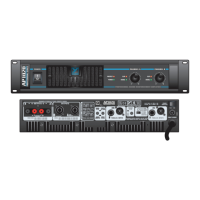
| Connectors (Inputs) | XLR, 1/4" TRS |
| Weight (lbs) | 28 |
| Weight (kg) | 12.7 |
| Type | Power Amplifier |
| Power Output (2 ohms) | 1000 Watts (per channel) |
| Bridged Mono Output (8 ohms) | 2000W |
| Protection | Thermal, DC |
| Connectors (Outputs) | Speakon |
| Dimensions (DWH, cm) | 48.3 x 8.9 x 40 |
| Weight | 28 lbs |
| Power Output | 2000 Watts (1000 Watts / Channel) |
| Input Impedance | 20 kOhms Balanced, 10 kOhms Unbalanced |
| Dimensions (DWH, inches) | 19 x 3.5 x 15.5 |
| Dimensions | 19 x 3.5 x 15.5 inches / 48.3 x 8.9 x 39.4 cm |