EasyManua.ls Logo

YORKVILLE AP6040 Service Manual

YORKVILLE AP6040
16 pages
To Next Page IconTo Next Page
Page #1 background imageLoading...
Page #1 background image
SERVICE MANUAL
AP6040
U.S.A.
Yorkville Sound Inc.
4625 Witmer Industrial Estate
Niagara Falls, New York
14305, USA
Voice: 716-297-2920
Fax: 716-297-3689
WORLD HEADQUARTERS
CANADA
Yorkville Sound Limited
550 Granite Court
Pickering, Ontario
L1W 3Y8 CANADA
Voice: 905-837-8481
Fax: 905-837-8746
Manual-Service-ap6040-00-2v4 • Dec 14/2020

Other manuals for YORKVILLE AP6040

Question and Answer IconNeed help?

Do you have a question about the YORKVILLE AP6040 and is the answer not in the manual?

YORKVILLE AP6040 Specifications

General IconGeneral
BrandYORKVILLE
ModelAP6040
CategoryAmplifier
LanguageEnglish

Summary

Important Safety Instructions

General Safety Symbols and Warnings

Explains symbols like lightning flash, exclamation point, and hot surface warnings.

Operational Safety Precautions

Covers warnings related to water, ventilation, heat sources, and proper usage.

Power Cord and Servicing Safety

Details power cord handling and servicing safety guidelines.

Product Panel Layout and Controls

Front Panel Overview

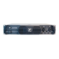
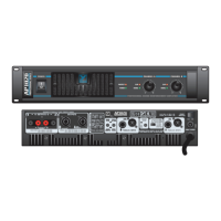
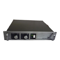
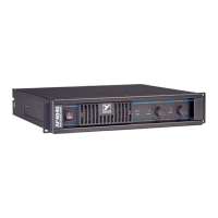
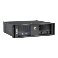
Details front panel controls, indicators, and power/protection features.

Rear Panel Connections and Settings

Describes rear panel inputs, outputs, and mode selection switches.

Technical Specifications

Performance and Electrical Characteristics

Lists power output, frequency response, hum, noise, THD, and slew rate.

Schematic and PCB Revision History

Schematic Diagram and Component List

Provides the main circuit schematic and lists components used in the design.

PCB Database History

Records changes and updates made to the Printed Circuit Board design over time.

Printed Circuit Board (PCB) Layout

Component Placement Diagram

Illustrates the physical arrangement of components on the PCB.

Assembly Guidance Notes

Provides general notes and instructions for PCB assembly.

Production and Assembly Notes

Mounting Hardware Specifications

Details specific hardware and torque for mounting various components.

Assembly Procedures and Details

Covers specific assembly steps like trimming leads and preparing for testing.

Revision Control and Component Data

PCB Version History Log

Tracks changes and updates made to the PCB design across different versions.

Component Lead and Pin References

Provides identification for component pinouts and lead configurations.

Detailed PCB Layout Diagrams

Top PCB Component Layout

Shows the component layout on the top side of the PCB.

Bottom PCB Component Layout

Displays the component layout on the bottom side of the PCB.

Detailed Production Mounting Hardware

Hardware for 5W Resistors and Transistors

Specifies hardware for mounting 5W resistors and transistors like Q25A/Q26A.

Hardware for TO3 Outputs and Other Components

Details hardware for TO3 outputs and other parts like capacitors.

Production Assembly Procedures

Component Mounting and Torque Specifications

Details specific hardware and torque for mounting components.

Assembly Details for Testing

Covers clamp details, torque, and breaking out boards for testing.

PCB History and Component Data

Comprehensive PCB Change Log

A detailed log of all PCB modifications and version updates.

Electronic Component Part References

Lists part numbers and package types for various electronic components.

Power Supply and Wiring Diagrams

Power Supply Schematic Details

Illustrates the power supply circuit and its essential components.

Connection Diagrams and Relay Circuitry

Shows wiring connections and the operation of the turn-on relay circuit.

PCB Layout and Wiring Details

Top PCB Layout and Wiring

Displays the layout and wiring on the top side of the PCB.

Bottom PCB Layout and Wiring

Shows the layout and wiring on the bottom side of the PCB.

Related product manuals