x channel high alarm is triggered when PVx (the present value of x
channel)>H.ALx; alarm releases when PVx<H.ALx - HYSx.
x channel low alarm is triggered when PVx<L.ALx;
alarm releases when PVx>L.ALx+HYSx.
HYS is set to avoid high frequent alarm on/off actions caused by process
input fluctuation. It also works at auto-tuning.
Alarm output
allocation
(Valid only for
E5 size)
For example, AOP1=43 that the low limit alarm of channel 1 is sent to AL2,
and high limit alarms sent to AL1
Define actual number of input channels. Setting range is 1~4.
When Cn=2, the lower window display the present value of channel 2 instead
of the channel number.
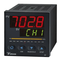
First display
channel setting
If several of AI-7048 has used, this parameter can define the AI-7048 to
display assigned channel number on display. For example, when Cno=6, the
controller will display channel number from 6~9. (6, 7, 8, 9)
Addition
function setting
1
Parameter “AF” was defined as below:
AF=A x 1 + B x 2 + C x 3 + D x 4
A=0; Normal speed in channel cycle display;
A=1; Faster speed in channel cycle display;
B=0; C=0;
D=0; Normal application; D=1; Change all of the low alarm to be high alarm;
Addition
function setting
2
Parameter “AF2” was defined as below:
AF=A x 1 + B x 2
A=0; Normal application;
A=1; Change all of the high alarm to be high deviation alarm; when deviation
value (PV – SV) > H.ALx, it will trigger the alarm. When (PV – SV) < H.ALx –
HYSx, alarm off, set the H.ALx value to maximum will disable the alarm
function.
B=0; Normal application;
B=1; Change all of the low alarm to be low deviation alarm; when deviation
value (PV – SV) < L.ALx, it will trigger the alarm. When (PV – SV) > L.ALx –
HYSx, alarm off, set the L.ALx value to minimum will disable the alarm
function.
Single channel relay module provides both normal open and normal close
output, while dual relay output module L5 only provides normal open output.
However, by parameter “nonc”, the NO output can be changed to NC output.
nonc = 0, AL1, AL2 (L5 is installed in ALM socket) are normal open output.
nonc = 127, AL1 and AL2 are normal close output
Loc=0, Allow to display and modify parameter “Loc” and the field parameters
which is defined in EP1~EP12 .
Loc=1, Allow to display and modify parameter “Loc”, and only display field
parameters, can’t modify them.
Loc=808, allow to display and set all parameters.
Note: This setting just effect on external display. Modify parameter by
communication was always allowed.
When configuration of the instrument is completed, most parameters will not
need to be set by field operators. Furthermore, field operators may not
understand many parameters, and may probably set parameters incorrectly
by mistake and make the instrument unable to work.
EP1~EP12 define 0~12 field parameters for operators’ use in parameter
table. Their parameter values are parameters except parameter EP itself, for
example, H.AL1, L.AL1, .etc,
Parameters from EP1 to EP12 can define 12 field parameters at most, if the
number of field parameters is less than 12(sometimes even none), it is
necessary to define field parameters from EP1 to EP12 in order, the first
unused EP should be set to none.
For example, four parameters of SP1 to SP4 (all channels’ setpoints) are
 Loading...