Do you have a question about the Yudian AI-518 and is the answer not in the manual?
Overview of the instrument's key capabilities and technologies, including accuracy and control algorithms.
Explains the structure and meaning of the product's ordering code for customization.
Details the modular design of the instrument and available module slots.
Describes the different module slots available in Al-518 series instruments.
Lists and describes common modules that can be installed for various functions.
Provides instructions on how to install or replace modules in the instrument.
Explains electrical isolation principles and considerations for different modules.
Offers detailed application scenarios for specific module types.
Lists detailed technical specifications including input types, ranges, accuracy, and resolution.
Illustrates the rear terminal layout and provides wiring diagrams for different instrument dimensions.
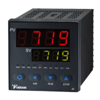
Describes front panel components, including display windows, keys, and indicators.
Visualizes the process for setting parameters, including password protection and table navigation.
Explains how to set values, navigate parameter tables, and modify settings.
Details the procedure for setting the setpoint (SV) in basic display status.
Guides users through accessing and modifying parameters in Field and System tables.
Explains how to perform auto-tuning for PID control for optimal performance.
Describes parameter lock levels and defining field parameters for user-defined access.
Provides a comprehensive list and description of all instrument parameters grouped by function.
Covers advanced features and specific operational notes for enhanced control.
Details the function and application of the single-phase phase-shift trigger output module.
Explains the feature to prevent nuisance alarms during instrument startup.
Describes switching between two setpoints using an external switch.
Explains establishing communication with a computer for control and monitoring.
Details using the instrument for temperature re-transmission or as a set current output.
| Brand | Yudian |
|---|---|
| Model | AI-518 |
| Category | Controller |
| Language | English |