Do you have a question about the Yudian AI-516 and is the answer not in the manual?
Key features and technologies of the AI-516/AI-516P controller.
Details on how to construct the product's ordering code and its components.
Overview of the instrument's modular design and available slots.
Describes the available slots for installing modules in different instrument dimensions.
Lists and describes various commonly used modules for the instrument.
Instructions on how to install and replace modules in the instrument.
Explains the electrical isolation principles for different modules.
Provides additional details on the applications of various modules.
Details the selectable input types and their corresponding input ranges.
States the accuracy of measurements and the resolution for different input types.
Covers temperature shift, sampling period, response time, and alarm functions.
Details control period, modes, output types, EMC, isolation, power, and ambient specs.
Lists front panel, cutout, and depth dimensions for various instrument sizes.
Presents wiring diagrams for different dimension instruments (A, B, C, E, F).
Details the specific wiring graph for D2 dimension instruments.
Shows the wiring graph for D5 dimension DIN rail mounting instruments.
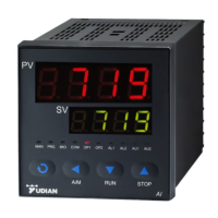
Describes the components and indicators on the instrument's front panel.
Explains basic display status and symbol meanings for alarms and errors.
Visual guide on how to navigate and set parameters.
Details how to set parameters and values, and adjust settings.
Step-by-step guide for performing the auto-tuning function.
Explains how to manage program execution (Run, Hold, Stop) on the instrument.
Explains the parameter lock function and how to define field parameters.
Lists and describes the various parameters grouped by function.
Details specific parameters like hysteresis, alarm display, output allocation, and control mode.
Details parameters for control mode, running status, acting method, auto tuning, and PID components.
Defines input specifications, display resolution, scaling, filters, and output types.
Covers output range, communication settings, advanced functions, password, and setpoints.
Details ramp slope, program number, power-on mode, program function, and field parameters.
Explains the single-phase phase-shift trigger output functionality.
Describes the function to block alarms during initial power-up.
Details how to connect and communicate with the instrument via computer.
Explains the communication protocol, instruction format, and address setup.
Lists Modbus register codes and their corresponding parameters for communication.
Details the mapping of Modbus addresses to instrument parameters.
Explains how to configure the instrument as a temperature re-transmitter or program generator.
Describes the 30-segment program control, slopes, and jump functions.
Explains program steps, timing, jump, run/hold, stop, and startup functions.
Details the curve fitting technology for smoothing process control curves.
Guides on setting up temperature-time programs using Ramp Mode.
Explains how to use Soak Mode for processes not requiring temperature slopes.
Describes how to arrange and manage multiple program curves for flexible operation.
| Model | AI-516 |
|---|---|
| Category | Controller |
| Display | Dual 4-digit LED |
| Accuracy | ±0.2%FS |
| Operating Temperature | 0-50°C |
| Dimensions | 96 x 96 x 100 mm |
| Mounting | Panel Mount |
| Input Type | Thermocouple, RTD |
| Output Type | Relay, SSR, DC current, DC voltage |
| Control Mode | PID, On-Off |
| Control Algorithm | PID algorithm |
| Power Supply | 100-240VAC, 50/60Hz |