Note 1: According to the voltage and current of load, choose a suitable varistor to protect the
thyristor.
A resistor-capacitor circuit (RC circuit) is needed for inductance load or phase-shift trigger output.
Note 2: SCR power module is recommended. A power module includes two SCRs, is similar to the
above dashed
square.
Note 3: K5 and K6 TRAIC trigger module only support 220
~
380VAC and 50Hz power.
2. DISPLAYS AND OPERATIONS
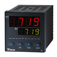
2.1 Front Panel Description
① Upper display window: Displays PV, parameter code, etc.
② Lower display window: Displays SV, parameter value, oralarm message
③ Setup key: For accessing parameter table and conforming parameter modification.
④ Data shift key, start auto tuning
⑤ Data decrease key, and also run switch
⑥ Data increase key, and also stop key
⑦ LED indicator: “MAN” led is non-applicable for AI-516 series.“RUN”led on, it mean AI-516P
running program. MIO, OP1, OP2, AL1, AL2, AU1 and AU2 indicate I/O operation of the
corresponding module. For example, when COMM led is lighting means that the instrument is
communicating with computer.
 Loading...