Check for parts online at w ww.yutrax.com or call 800-345-6007 M-F 8-5
4
Operator's Manual
TX210 UTV JUMP SEAT
ASSEMBLY INSTRUCTIONS
IMPORTANT ASSEMBLY TIP:
Do not tighten any nut and bolt combinations completely
until all parts are assembled together! Finger tighten plus
one turn of a wrench only! This will temporarily hold the
lock- nut on the bolt while helping alignment of all parts!
After all parts are assembled together, all nut and bolt
combinations must be completely tightened.
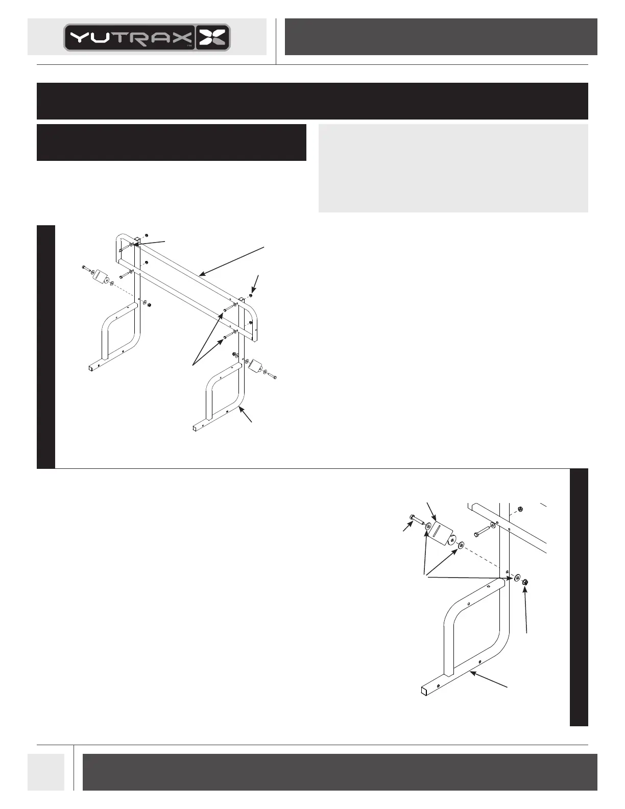
STEP 2
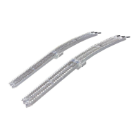
STEP 3
3. Attach the two seat belt receivers (48798) to the two upright frames using
(2) provided 5/16-18 x 1-3/4” hex head bolts, (6) 5/16" steel washers, and
locknuts. SEE FIGURE 1B. Receivers should both be mounted on what would
be the “outer” sides of the upright frames when unit is completely assembled.
locknuts
upright frames
backrest
frame
1/4-20 x 2” bolts
steel washers
steel washers
locknut
5/16-18 x 1-3/4” bolt
seat belt receiver
upright frame
1. Study and measure the width of your UTV box. This UTV Jump Seat has
been designed to t most brands of UTV’s. The upright frames (A682) can be
mounted at 26”, 28” or 30” widths. DO NOT tighten all nut & bolt assemblies
completely!
NOTE: There are multiple hole locations in backrest frame, seat stop tube
and seat frame.
It all depends on the mounting positioning of Jump Seat in relation to your
UTV box. Study your UTV box to determine the best mounting locations that
will not interfere with any frame rails of the UTV.
2. Attach the backrest frame (A681) to the two upright frames using (4) provided
1/4-20 x 2” hex head bolts, 1/4” steel washers, and locknuts. SEE FIGURE 1A.
FIGURE 1A
FIGURE 1B
• 7/16 IN Wrench - Qty. 2
• 1/2 IN Wrench - Qty. 2
• 21/64 IN Drill Bit - Qty. 1
TOOLS FOR ASSEMBLY