6. Use a 1/4 hex wrench to hold the servo adjustment screw in place, and a 9/16 hex wrench to tighten
servo lock nut (115). Torque to 37 N•m [27 lbf•ft].
7. Shut down prime mover and remove previously installed gauges and fittings. Plug ports MA, MB, M4,
and M5.
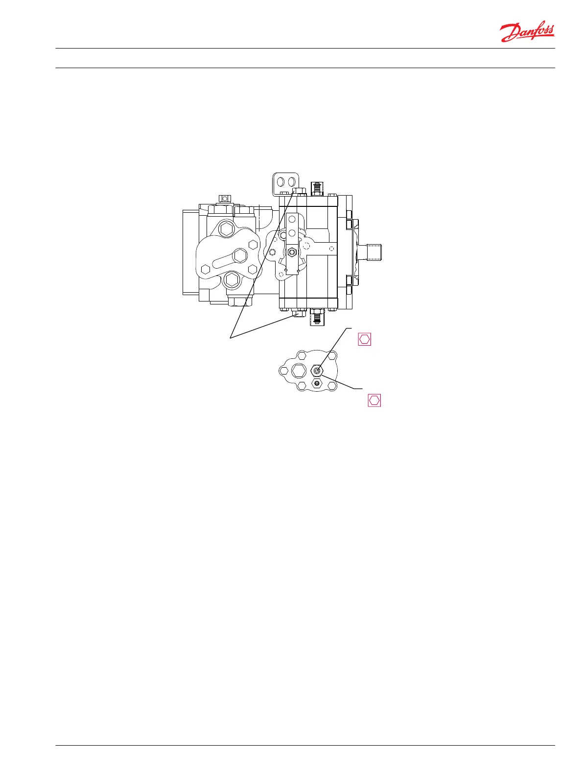
Servo neutral adjustment
P10 6 6 30E
908
1/ 4 in
115
11/ 16 in
Co n n e c t Po r t s
M4 and M5
Manual Displacement Control Neutral-Return Bracket Adjustment
With the pump properly plumbed, primed, and mounted on a vehicle or test stand, use the following
procedure to adjust the pump displacement control to neutral position. If pump is on a vehicle, securely
block the wheels to prevent movement. Check swashplate mechanical neutral adjustment before
adjusting control bracket. Refer to previous topic Swashplate neutral adjustment on page 22 for
instructions. If swashplate neutral is properly adjusted and system is not in neutral, adjust MDC bracket as
described below.
Measured data
•
Servo pressure at M4
•
Servo pressure at M5
•
Pressure differential between M4 and M5 (optional)
Procedure
1. Attach 20 bar [300 psi] gauge to each servo gage port M4 and M5. Run prime mover at normal
operating speed.
2. Using a 3/8 in. hex wrench, loosen screw (1210) allowing the neutral bracket to move, but not freely.
3. Start prime mover and slowly accelerate to normal operating rpm.
4. Using your hand, press neutral bracket towards the pump housing, and rotate it until one of the servo
pressure gages indicates an increase in pressure. Note position of bracket. Rotate neutral bracket in
opposite direction until the other servo pressure gage indicates an increase in pressure. Note position
of bracket. Rotate neutral bracket half way between the two positions.
5. Holding the neutral adjustment bracket in place, use a 3/8 in. hex wrench to tighten screw (1210).
Torque to 14 N•m [10 lbf•ft].
Service Manual
Series 40 M46 Variable Pumps
Adjustments
11026743 • Rev BA • June 2014 23