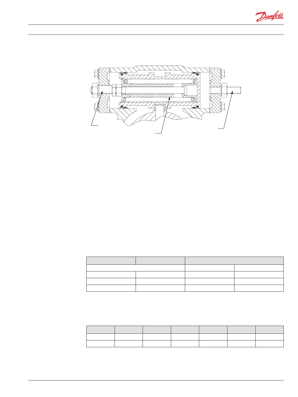
M46 Displacement limiter (side #2)
Neut ral
adj ust ment
screw
Fi xed
displacement
limiter
Adjustable
displacement
limiter screw
P10 0 592 E
Auxiliary Mounting Pads and Auxiliary Pumps
Auxiliary mounting pads are available on all pumps. A sealed shipping cover is included as standard
equipment on all mounting pads.
An O-ring seals the auxiliary pump mounting flange to the pad. The drive spline is lubricated (flooded)
with oil from the main pump case.
Spline specifications and torque ratings are shown in the accompanying table.
•
All auxiliary mounting pads meet SAE J744 specifications
•
Do not exceed the maximum pump input shaft rating shown in the Shaft availability and torque
ratings table in the Shaft Options section
•
Applications subject to severe vibratory or high G loading require an additional structural support.
This is necessary to prevent leaks and possible mounting flange damage. Refer to Mounting flange
loads in the System Design Parameters section, for additional information
Auxiliary mounting pad specs
Internal spline size Pad size Maximum Torque Rating
Nm [in lbf]
9T 16/32P SAE A 107 [950]
11T 16/32P SAE A 147 [1300]
13T 16/32P SAE B 248 [2200]
The drawing and table below show the dimensions of the auxiliary pump mounting flanges and shafts.
Auxiliary pump mounting flanges and shafts with the dimensions noted are compatible with the auxiliary
mounting pads on the Series 40 pumps.
Auxiliary pump mating dimensions mm [in.]
Pad size P B C D E F
SAE A 82.55 [32.50] 6.35 [0.250] 12.70 [0.500] 58.2 [2.29] 15.0 [0.59] 13.5 [0.53]
SAE B 101.60 [4.000] 9.65 [0.380] 15.2 [0.60] 53.1 [2.09] 17.5 [0.69] 14.2 [0.56]
Technical Information Series 40 M46 Pumps
Options
L1001029 • Rev BG • May 2015 35