Series 3 Technician’s Installation and Service Training Manual
Adjusting Potentiometers
Series 3 Technician’s Installation and Service Training Manual
Adjusting Potentiometers
Series 3 Adjusting Potentiometers
ZAP Series 3
Simply Logical
ZAP Controls
100 Waterloo Blvd. Anglesey Business Park, Littleworth Road, Cannock, Staffordshire, England
UK Contact 011-44-154-387-9444 sales@zap-uk.com
USA Contact 931-510-4432 sales@zap-america.com
USA Tech Support 931-510-4432 via telephone or text
Online www.zap-uk.com
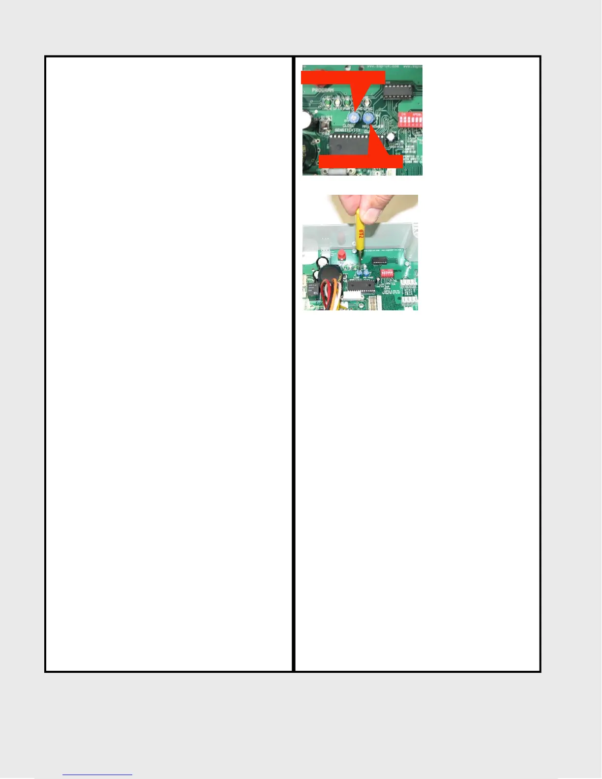
Adjusting potentiometers
There are two adjustable potentiometers on the
control board that allow you to adjust the
power to the motor and closing sensitivity of
the close cycle. (Figure A)
The screwdriver slot of each potentiometer
adjusting screw slot has an arrow on the end to
indicate its position.
It only rotates clockwise to approximately the
4 o’clock position indicator and counter-
clockwise to the 8 o’clock position indicator.
Turning past the internal stops at these points
will break the potentiometer the and require
circuit board replacement.
Use only a small slotted technicians
screwdriver, no larger than the slot provided to
avoid damaging the potentiometer. (Figure B)
The factory setting for this device is with the
arrow at the end of the screwdriver slot
pointing at the 1:00 o’clock position
Only make small incremental turns equivalent
to 1 clock position at a time.
The close sensitivity adjusts counter-clockwise
to reduce the sensitivity (increase the closing
force) of the operator or clockwise to increase
the sensitivity (decrease the closing force) of
the operator.
The Max Power Clamp adjust the overall power
output to the motor. It adjust counter-clockwise
to increase the power output, and clockwise to
decrease the power output to the motor.
You should never have to turn the
potentiometers past the 9 o’clock position
indicator to cause proper functioning of the
operator. If so, there is problem with either you
operator sizing requirement or with the door
itself.
Contact tech support with any questions.
Max Power Clamp
Close Sensitivity
(Figure A)
(Figure B)
70
 Loading...