EN - 13
3. Press MODE to conrm or
Press and hold MODE to cancel
the operation.
When no button is operated for
10 seconds any adjustment made is
cancelled. The unit will return to normal
operating mode.
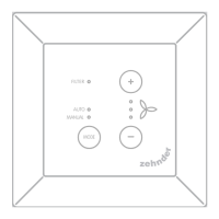
7 Filter status
The lter status is represented by the
lter LED:
■ OFF: Filter OK / No failure;
■ BLINKING: Order replacement
lter;
■ ON: Replace lter.
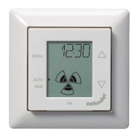
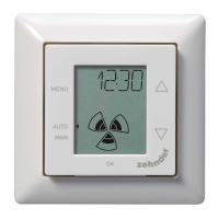
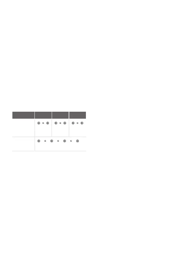
8 Malfunction alerts
Menu item
LED 1 LED 2 LED 3
HRU
initializing /
HRU service
mode
ERROR (all
LEDS are
blinking)
Initalisation /Service mode error: LED 1,
LED 2 and LED 3 are blinking. Air ow
cannot be set and there is no ventilation.
Check HRU display and HRU manual to
x this error.
Error: Any other HRU or system
malfunction, all indicator LEDs on the
device are blinking. Check HRU display
and HRU manual to x this error.
9 Installation
Disconnect the ventilation unit from the
main power before installing the device.
Always follow local safety regulations.
During assembly, ensure that ALL
screws are tight.
If ordered (g 4.1 - 4.5):
1. Attach the wall-mounting casing I
with the plugs H and screws G to
the wall.
2. Fasten the wall frame A with the
screws (F) on the wall, wall-mounting
casing (I) or mounting plate (E).
3. Put the communication cable
through the design frame X and
resize window (D).
4. Plug in the communication cable
(g 4.5), to connect the ventilation
unit and the device.
5. The cable requirements are:
■ 2x twisted pair, unshielded,
(preferably in compatible colours
with the colour coding of the
connectors);
■ Stiff (solid) wires (not exible
type), for push-in clamps;
■ Specication according to DIN
VDE 0281: J-Y(St)Y 2 x 2 x 0,6.
6. Attach the device (B) (with the
design frame X and the resize
window D) with the screws E to
the frame A.
To replace, use any of the following
screws:
■ Hardened and galvanized steel
screw 2.2 x12 PT10;
■ M2.2x 12 cross recess plan
plas-x45°.
7. Push the cover C into its place.
10 Commisioning
Turn ON the main power of the
ventilation unit. When the device rst
starts, the LED 1, LED 2 and LED 3 are
blinking.
 Loading...