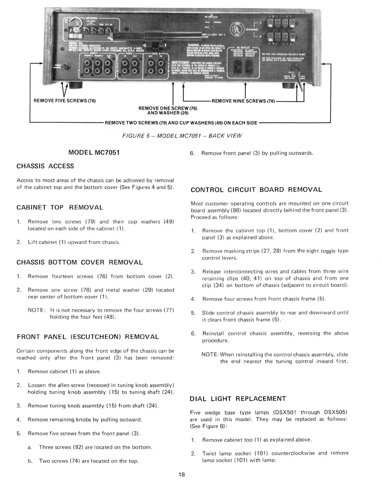
REMOVE FIVE SCREWS (76)
REMOVE ONE SCREW (76)
AND WASHER (29)
REMOVE NINE SCREWS (76)
REMOVE TWO SCREWS (79) AND CUP WASHERS (49) ON EACH SIDE
FIGURE 5 - MODEL MC7051 - BACK VIEW
MODEL MC7051
CHASSIS ACCESS
Access to most areas of the chassis can be achieved by removal
of the cabinet top and the bottom cover (See Figures 4 and 5).
CABINET TOP REMOVAL
1.
Remove two screws (79) and their cup washers (49)
located on each side of the cabinet (1).
2.
Lift cabinet (1) upward from chassis.
CHASSIS BOTTOM COVER REMOVAL
1.
Remove fourteen screws (76) from bottom cover (2).
2.
Remove one screw (76) and metal washer (29) located
near center of bottom cover (1).
NOTE:
It is not necessary to remove the four screws (77)
holding the four feet (48).
FRONT PANEL (ESCUTCHEON) REMOVAL
Certain components along the front edge of the chassis can be
reached only after the front panel (3) has been removed:
1.
Remove cabinet (1) as above.
2.
Loosen the alien screw (recessed in tuning knob assembly)
holding tuning knob assembly (15) to tuning shaft (24).
3. Remove tuning knob assembly (15) from shaft (24).
4. Remove remaining knobs by pulling outward.
5. Remove five screws from the front panel (3).
a. Three screws (82) are located on the bottom.
b. Two screws (74) are located on the top.
6. Remove front panel (3) by pulling outwards.
CONTROL CIRCUIT BOARD REMOVAL
Most customer operating controls are mounted on one circuit
board assembly (98) located directly behind the front panel (3).
Proceed as follows:
1.
Remove the cabinet top (1), bottom cover (2) and front
panel (3) as explained above.
2.
Remove masking strips (27, 28) from the eight toggle type
control levers.
3. Release interconnecting wires and cables from three wire
retaining clips (40, 41) on top of chassis and from one
clip (34) on bottom of chassis (adjacent to circuit board).
4. Remove four screws from front chassis frame (5).
5. Slide control chassis assembly to rear and downward until
it clears front chassis frame (5).
6. Reinstall control chassis assembly, reversing the above
procedure.
NOTE:
When reinstalling the control chassis assembly, slide
the end nearest the tuning control inward first.
DIAL LIGHT REPLACEMENT
Five wedge base type lamps (DSX501 through DSX505)
are used in this model. They may be replaced as follows:
(See Figure 6):
1.
Remove cabinet top (1) as explained above.
2.
Twist lamp socket (101) counterclockwise and remove
lamp socket (101) with lamp.
18
 Loading...