3
Installation manual
■
TheWSserieshasbeenapprovedwithaowsensitivityclassU0/D0.
However,toachievethebestmeasurementresults,werecommend
observingnationalregulationsandrecognisedrulesoftechnology.
■
ForWSseriesisrecommendedastraightinletsectionofatleast5xDN.
Ifthereisnosuicientinletsectionbepresent,orbehindpipeelbow,
werecommendtouseahoneycombrectierfromZENNER.
■
Ideally,atleast2xDNshouldbeavailableastheoutletsection.
■
Beforeinstallingthemeter,thepipingmustbethoroughlyushedout.
■
Thepipediametershouldnotbereduced,directlyinfrontandbehind
themeter.
■
Flangegasketsmustnotextendintothepipe.
■
Itmustbeensuredthattheowdirectionofthemetermatchesthatof
thepipe.
■
Valvesorotherowregulatorsshouldbeinstalled,wherepossible,
behindthemeter.
■
Themetershouldbeinstalled,wherepossible,atthehighestpointofthe
pipeinstallationsothatairbubblesarenotabletoforminthemeterand
thepipeisalwayscompletelylled.
■
Ifnecessary,themetershouldbeprotectedbyacorrespondinglter,
sothatnoforeignparticles,suchasstonesorsand,areushedintothe
measuringinstrumentandcausedamage.
■
Themetermustbeprotectedagainstpressuresurgesinthepipe
network.
■
Themaximumwatertemperaturemustnotexceedthepermissible50°C
forcoldwater.
■
Inordertopreventdamagetothemeasuringinsertcausedbypressure
surges,thepipemustbeslowlylledfollowinginstallation.
■
Itmustbeensuredthatthemeterisinstalledinade-energisedstatein
thepipe.Inthecaseofaninstallationthatisnotde-energised,thehous-
ingofthemeasuringinstrumentcanbedamagedandwatermayescape.
■
Thepipelinepressuremustnotexceedthemaximumworkingpressure
ofthemeter,asthiscanleadtoleaksanddamageofthemeter.
■
Topreventthedisassemblyofthemeterwerecommendtosecurethe
connectioninterfacewithasafetydevice(adhesivelabel,seal,etc.).
Installation instructions for the replacement of the metrological unit
■
Theexchangeofexchangeablemetrologicalunits(measuringinsert
shouldonlybeperformedbytrainedspecialiststa.
■
Beforechangingthemeasuringinsert,thepipemustberinsedcarefully
shutothepressuresideandemptythepipe.
■
Thecomplianceoftheinterfacesmarkingonthemeasuringandatthe
speciedinterface(body)(WS1)mustbechecked.
■
Aerdisassemblyofthemeasuringinsertoldgaskets/sealsmustbe
removed.Thesealingsurfacesmustbecleanedandcheckedfordamage.
■
Itisimportanttoensurethattheinletareaisfreeofdeposit,beforea
newmetrologicalunitisinstalled,becauseasthesecanleadtodevia-
tionsofthemeasurementresult.
■
Useonlythegenuineseals,whicharedeliveredtogetherwiththemea-
suringinsert.Thesehavetobecheckedpriortoinstallationfordamage
andt.
■
Whenusinglubricants/assemblypastese.g.fortheseals,itmustbe
ensuredthatthesearesuitableforcontactwithdrinkingwater.
■
Tightenthescrewsofthemeasuringunitevenlycrosswise(M12:DN50–
DN100=60Nm;M20:DN150–DN200=100Nm).
■
Topreventthedisassemblyofthereplacablemeasuringinsert,itmust
beconnectedwiththeconnectioninterface(housing)byasealingwire.
Thedeclarationofconformityisincludedinthedelivery.Thelatestinforma-
tiononthisproductcanbecalledupfromwww.zenner.com
Technical data
Nominal diameter DN mm 50 50 65 80 80 100 150 200
Permanent Flowrate Q
3
m³/h 25 40 40 63 63 100 250 400
Standard measuring
range
1
Q
3
/Q
1
R R100H
Operating pressure, max. MAP/PN bar 16 16 16 16 10 16 16 16
Pulse value Reed l/pulse 100 100 100 100 100 100 1000 1000
Pulse value
of the modulator disc
l/pulse 10 10 10 10 10 10 100 100
Total height approx.
2
mm 228 228 238 292 292 309 416 525
Installation height of the
measuring unit
mm 270 270 270 370 370 382 557 743
Weight approx. kg 13 13 18 21 21 24.4 57.6 94.3
1
Othermeasuringrangesandoveralllengthsonrequest.
2
TotalheightWSDE+18mm
Remark
Thisinstallationmanualisintendedforqualiedspecialistsonly.Basic
installationstepsarethereforenotdescribed.
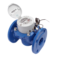
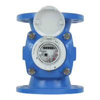
Permissible installation positions
TheWSseriesisintendedforinstallationinthehorizontalpositiononly.
English
Subjecttotechnicalmodications.Weacceptnoliabilityforanyerrorsormisprints.
ZENNER International GmbH & Co. KG
Römerstadt6|66121Saarbrücken|Germany
Phone +4968199676-30
Fax +4968199676-3100
E-Mail info@zenner.com
Internet www.zenner.com
 Loading...