12
www.zephyronline.com
1
2
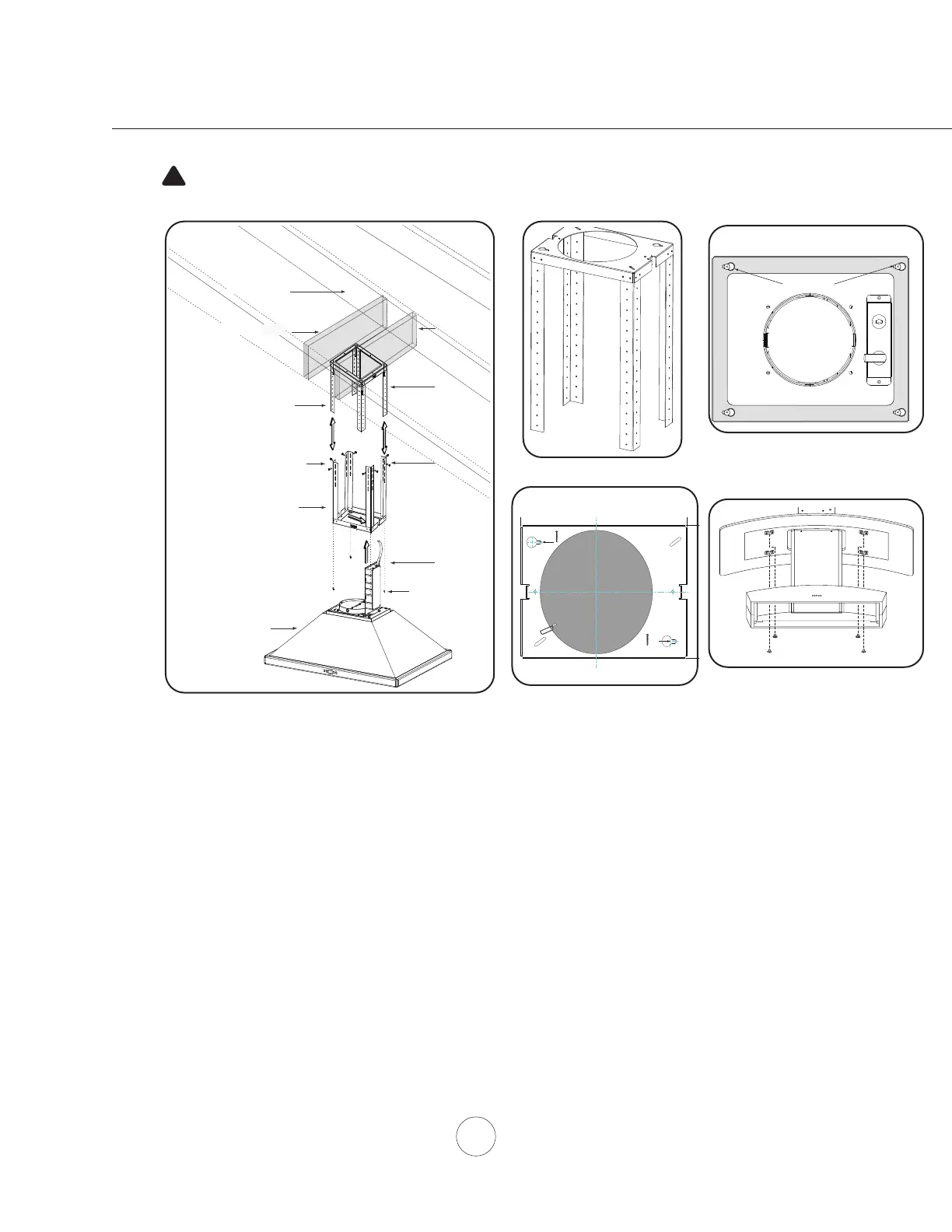
Ceiling Joists
Wood Blocking
Top Support Frame
Support Frame Arm
Bottom Support Frame
Hood Body
3
Mounting Screws
(pre-installed)
4
Installation – Mounting the Hood
'HWHUPLQHPRXQWLQJORFDWLRQRQFHLOLQJDQGWHPSRUDULO\WDSHSDSHUWHPSODWHLQFOXGHGZLWKWKHKRRGWR
the ceiling. Cut out internal shaded area of template to allow the ducting and electrical to pass through.
,IQHFHVVDU\DGGZRRGEORFNLQJPLQ´[´WRFHLOLQJMRLVWVORFDWHGEHKLQGWKHGU\ZDOOWRUHLQIRUFHWKH
PRXQWLQJORFDWLRQ),*$6HFXUH0[´ZRRGVFUHZVWRSRLQWV$DQG%RIWKHSDSHUWHPSODWH),*
*'RQRWFRPSOHWHO\WLJKWHQVFUHZVOHDYHDSSUR[´H[SRVHG
2. Remove screws securing top and bottom support frames together. Adjust support frame to accomodate the
GHVLUHGKRRGKHLJKWDQGUHDVVHPEOHWKHIUDPHXVLQJWKHSUHYLRXVO\UHPRYHGVFUHZVVFUHZVIRUHDFK
VXSSRUWIUDPHDUP),*$
/LIWVXSSRUWIUDPHDVVHPEO\XSWRWKHFHLOLQJPDNLQJVXUHWKHZRUG³IURQW´RQWKHWRSVXSSRUWIUDPHIDFHVWKH
IURQWRIWKHKRRGZKHUHWKHFRQWUROVZLOOEHORFDWHG),*%7KHNH\KROHVRQWKHWRSVXSSRUWIUDPHVKRXOG
FRYHUWKHZRRGVFUHZVSUHYLRXVO\LQVWDOOHGLQWKHFHLOLQJ6OLGHVXSSRUWIUDPHWRZDUGVQDUURZHQGRINH\
KROHVWRORFNWKHIUDPHLQSODFH,QVWDOOWKHODVW0[´ZRRGVFUHZVZLWKZDVKHUVLQWRWKHWZRUHPDLQLQJ
corners of the top support frame to secure it to the ceiling. Tighten all screws.
=5(21/<5HPRYHDOXPLQXPPHVK¿OWHUVIURPKRRG3ODFHFDQRS\RYHUEORZHUKRXVLQJDQGVHFXUHLWWR
KRRGERG\XVLQJ[SDQKHDGPDFKLQHVFUHZVWKURXJK¿OWHURSHQLQJ),*/
/LIWKRRGDQGDOLJQWKHSUHLQVWDOOHGPRXQWLQJVFUHZVORFDWHGRQWRSRIWKHXQLWERG\),*$ZLWKWKH
NH\KROHVRQWKH%RWWRPRI6XSSRUW)UDPH),*&6OLGHKRRGWRZDUGVWKHQDUURZHQGRINH\KROHVWRORFN
LQWRSODFH+DQGWLJKWHQHDFKRIWKHVFUHZVZLWKDVFUHZGULYHUWRVHFXUHKRRGWR%RWWRP6XSSRUW)UDPH
)XUWKHUVHFXUHERWWRPVXSSRUWIUDPHWRXQLWERG\E\RQH0[VDIHW\VFUHZ),*)SJ
+RRGLVLQWHQGHGWREHPRXQWHGWRD¿QLVKHGFHLOLQJ
CAUTION: At least two installers are
required due to the weight and size of the
hood.
!
Bottom Support Frame
(secures to top of blower housing)
Key Holes
front - facing controls
back
FIG. A
FIG. C
FIG. B
Side
Front
XP022220
A
B
Cut-Out Shaded Area
FIG. G
FRONT
FIG. L
 Loading...