Do you have a question about the Zepro Z 1500-135 and is the answer not in the manual?
CE marking compliance for European market and product approval according to EN standards.
Specifies approved hydraulic oil types and grades for the lift system.
Conditions for valid guarantee and explanation of model naming conventions.
Guidelines on parts not to be painted to avoid damage to seals and cables.
Removing transport plug and ensuring safe movement clearance for cylinders.
Prohibition of attaching third-party equipment to the lift system to ensure safety.
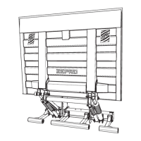
Steps for calculating dimensions and installing the main support frame.
Procedures for connecting electrical components like control devices and cables.
Steps for fitting the platform, seals, end stops, and cylinders.
Procedure for applying identification and safety decals.
Explains C, D, A, and H dimensions for lift installation planning.
Steps for creating necessary cut-outs in the rear beam for platform arms.
Detailed steps for mounting the support frame using jigs and chassis brackets.
Instructions for routing the control power cable safely from cab to lift.
Guidelines for positioning and fitting control devices for operator safety.
Cabling and routing for warning lights and foot controls.
Proper routing, protection of main power cable, and fuse box installation.
Using cable grommets and meeting underrun protection requirements.
Fitting armstops, installing angle sensor, and sealing strips.
Lubricating and fitting the platform, adjusting tilt cylinders.
Setting downward tilt angle and fitting cylinder boots.
Procedures for purging cylinders and the transport lock mechanism.
Connecting the control card for temporary lift operation and safety warning.
Steps to access and service the hydraulic unit and control card.
Routing and connecting the controller to the control card.
Electrical and hydraulic diagram for MA Autotilt models.
Electrical and hydraulic diagram for MA models.
Electrical and hydraulic diagram for DA models.
Diagram for connecting warning lights and foot controls.
Wiring diagrams for various control devices.
Table detailing sensors, inputs, and their functions for MA Autotilt.
Functional schematics for MA Autotilt lift with inclinometer.
Detailed explanation of the autotilt up and down functions.
Limitations on control device use and activation zones.
Table detailing sensors, inputs, and their functions for MA models.
Functional schematics for MA models, including control device restrictions.
Limitations on control device use and activation zones.
Table detailing sensors, inputs, and their functions for DA models.
Functional schematics for DA models, including control device restrictions.
Limitations on control device operation and activation zones.
Control card power save mode and explanation of display/LED indicators.
Interpretation of display codes for system status and configurations.
Listing and explanation of fault codes for troubleshooting purposes.
Control device status, locking, and recommended supply voltage ranges.
Instructions for affixing load capacity diagrams on the vehicle body.
Details on the identification plate and work area sticker placement.
Application of warning tape on platform edges and danger area sticker.
Guidelines for affixing controller identification stickers.
Identifies lubrication points and recommended service intervals.
Procedure for checking and topping up hydraulic fluid.
Procedure for static load tests, including deformation and drift checks.
Testing lift operation with maximum load and overload conditions.
Verification of all safety functions of the tail lift.
Step-by-step instructions for removing the tail lift from a vehicle.
List of weights for various lift components.
Electrical power requirements and recommended conductor sizes.
Guidelines for battery maintenance and charging.
Graphical representation of load capacity limits.
Specifications for torque values for various fasteners.
| Brand | Zepro |
|---|---|
| Model | Z 1500-135 |
| Category | Industrial Equipment |
| Language | English |