Do you have a question about the Zepro Z 2000-175 and is the answer not in the manual?
Instructions regarding painting of piston rods, cylinder covers, hoses, and cables.
Ensuring clearance for moving cylinders and platform tilt limits for safety.
Prohibits attaching third-party equipment to Zepro tail lifts due to interference risks.
General warnings for installation, including platform ground level reach and approved installation kits.
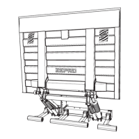
Detailed steps for mounting the support frame, including jig usage and alignment.
Instructions for fitting control devices, including placement and distance requirements.
Instructions for routing the main power cable, including protection and earthing.
Requirements and installation of underrun protection for vehicle chassis.
Procedures for checking, lubricating, and fitting the platform to the arms.
Detailed steps for removing the protective cap and accessing the hydraulic unit.
Diagrams for connecting cabin switch and open platform alarm for truck and trailer.
Diagrams showing connections for various common control devices.
Schematic drawing for config 14, showing lift with inclinometer and Autotilt functions.
Schematic drawing for MA models, config 14, detailing functions and illustrations.
Schematic drawing for DA models, detailing functions and illustrations.
Explains fault codes displayed for system errors and their meanings.
Describes behavior and fault codes for control devices, including coil control device LEDs.
Instructions for affixing load diagrams for appropriate lift models.
Lists lubrication points that must be greased on installation and regularly thereafter.
Details on performing deformation and drift tests with static load.
Procedures for dynamic load tests with max load and overload.
Checklist for testing all tail lift safety functions.
Power consumption data and recommended conductor sizes for 12V and 24V systems.
Specifies torque values for various installation points.
| Brand | Zepro |
|---|---|
| Model | Z 2000-175 |
| Category | Industrial Equipment |
| Language | English |