Do you have a question about the Zepro ZL 2000-135 and is the answer not in the manual?
General warnings and notes about markings for potential risks.
CE marking and manufacturer guarantees for the European market.
Specifications and recommendations for hydraulic oil.
Explains model identification codes for Z and ZL series lifts.
Precautions for painting components to avoid damage to gaskets and hoses.
Safety guidelines for clearance around moving cylinders to prevent collisions.
Warning against attaching unauthorized third-party equipment to the tail lift.
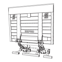
Steps involved in installing the main support frame of the lift.
Procedures for making the necessary electrical connections.
Steps for correctly fitting the platform onto the lift arms.
Defines C dimension (support frame to floor) crucial for installation.
Defines D dimension (body rear edge to support frame) for installation.
Defines A dimension (space for rear member) related to lift arm position.
Detailed steps for positioning and mounting the support frame.
Routing and connecting the control power cable from the driver's cab.
Installation, positioning, and connection of control devices.
Routing the main power cable from lift to battery and ensuring proper earthing.
Vehicle chassis requirements for compliant underrun protection.
Procedures for adjusting the tilt angle of the lift cylinders.
Procedure to set the downward tilt angle for safety, max 10°.
How to connect the control card for temporary operation.
Steps to safely disconnect the temporary setup.
Procedures for removing protective caps and accessing components.
Steps for connecting a control device to the control card.
Schematic for MA models with autotilt.
Electrical and hydraulic schematic for MA models.
Electrical and hydraulic schematic for DA models.
Diagrams illustrating connections for various control devices.
Lists and describes sensors and inputs for MA Autotilt models.
Schematic showing lift operation with inclinometer for config 14.
Detailed explanation of the autotilt function for config 14.
Lists and describes sensors and inputs for MA models.
Schematic for MA, config 14, detailing opening function.
Activation zone for quick opening function for MA.
Lists and describes sensors and inputs for DA models.
Schematic for DA, covering opening and lower functions.
Limits on control device usage based on platform angle for DA.
Explanation of the control card display, lights, and LEDs.
Explains display codes for configuration, status, and sensor indications.
Explanation of fault codes displayed on the control card.
Instructions for affixing load diagrams for correct capacity and CG.
Details on the identification plate's content and placement.
Guidance on affixing controller stickers in standard and reversed versions.
Identifies critical lubrication points and required service frequency.
Procedure for checking and topping up hydraulic oil levels.
Procedures for deformation and drift testing under static load.
Tests for maximum load, overload, and safety functions.
Verification of all safety features and indicators.
Lists the weights of various lift components.
Details power requirements and recommended conductor sizes.
Specifies torque values for critical fasteners during installation.
| Brand | Zepro |
|---|---|
| Model | ZL 2000-135 |
| Category | Industrial Equipment |
| Language | English |