Do you have a question about the Zepro ZHDN 2500-150 and is the answer not in the manual?
Safety warning regarding clearance for moving cylinders and tilt angle limits.
Warning against attaching third-party equipment to Zepro tail lifts due to system interference.
Safety warnings regarding platform installation height and approved installation kits.
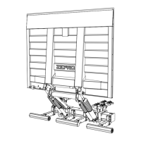
Steps for installing the support frame, including dimensions and mounting.
Steps for making electrical connections for control devices and power.
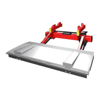
Steps for installing the platform, seals, end stops, and armstops.
Warning against attaching third-party equipment to Zepro tail lifts due to system interference.
Procedure for fitting and positioning underrun protection to meet statutory requirements.
Procedure for adjusting the tilt angle of the cylinders before fitting to the platform.
Procedure for adjusting the downward tilt angle to a maximum of 10°.
Table and explanation of fault codes displayed by the connection unit for troubleshooting.
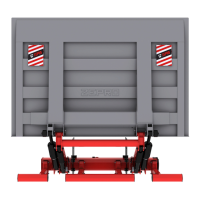
Details on the load diagram decal, its placement, and purpose.
Placement of the 'danger area' decal warning about the zone between platform and vehicle.
List of lubrication points and recommended lubricant for installation and annual service.
Procedure for checking and topping up hydraulic fluid levels.
Procedure for static load testing to check for deformation and drift.
Procedures for dynamic load testing with maximum load and overload.
Checklist for testing all safety and operating functions of the tail lift.
Table of power consumption for components and recommended conductor sizes.
Diagram showing the load capacity of the lift at different reach distances.
Diagrams indicating specific torque values for various bolts during installation.
| Brand | Zepro |
|---|---|
| Model | ZHDN 2500-150 |
| Category | Automobile Accessories |
| Language | English |