Do you have a question about the Zepro ZT 200-140 and is the answer not in the manual?
Specifies requirements for underrun protection, including distance limits.
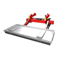
Instructions for positioning and securing slide profiles on the trailer chassis.
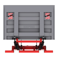
Step-by-step guide for mounting the working position lock mechanism.
Details the process of attaching the slider frame to the vehicle chassis, including bolt placement.
Guidelines for positioning and connecting control devices for safe operation and visibility.
Schematic diagram showing electrical and hydraulic connections for ML models.
Schematic diagram for DL models, illustrating electrical and hydraulic system layout.
Diagram for ML models with hydraulic auto-tilt, showing electrical and hydraulic circuits.
Illustrates various control device models (CD5, CD3, CD14, CD11, CD9, CD10, CD13) and their connections.
Functional schematic for Config 1, detailing lift functions and control device inputs/outputs.
Functional schematic for Config 3, detailing lift functions and control device inputs/outputs.
Details codes displayed on the control card for identifying operation status and faults.
Lists and explains fault codes (L, H, E, F, A) for troubleshooting lift issues.
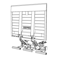
Instructions for installing and adjusting the working position sensor and stop plate.
Guidance on checking clearance for moving parts during operation to prevent conflicts.
Lists 13 specific points requiring greasing at least 8 times per year.
Table for static loading tests at 600mm load centre, specifying capacity and distance.
Procedures for testing with nominal load and overload.
Checks for safety functions like warning lamps, cabin switch, fuse, overflow valve, and markings.
| Brand | Zepro |
|---|---|
| Model | ZT 200-140 |
| Category | Automobile Accessories |
| Language | English |