Do you have a question about the Zepro ZTS 200-140 and is the answer not in the manual?
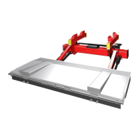
Details the electro-hydraulic drive system, platform support, safety valves, and cylinder features.
Illustrates maximum load capacities and lifting ranges for various models.
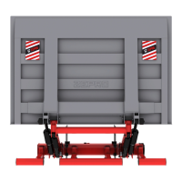
Specifies legal dimensions for underrun protection and platform positioning.
General guidelines for optimal slider profile placement to ensure platform folding.
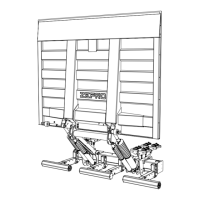
Illustrates potential installation problems and preferred configurations for sliding lifts.
Lists key points to consider for correct sliding lift installation geometry.
Instructions for positioning and securing slide profiles on trailer chassis.
Procedure for mounting the working position lock mechanism.
Procedure for adjusting the position of the working position lock.
Details on attaching the slider frame to the vehicle chassis.
Comprehensive diagram of the lift's electrical and hydraulic systems.
Information on power save mode, operating status display, and LED indicators.
Lists and explains fault codes related to control devices, outputs, and internal faults.
Details on resetting fault codes and acceptable voltage ranges for operation.
Details on greasing intervals for bearings and platform locks, and hydraulic oil types.
Procedure for static loading tests to check for platform deformation.
Tests for dynamic load capacity and verification of safety functions.
Step-by-step instructions for safely dismantling the tail lift from a vehicle.
| Brand | Zepro |
|---|---|
| Model | ZTS 200-140 |
| Category | Automobile Accessories |
| Language | English |