Triple IR Flame Detectors FV400
Fixing Instructions Doc. version 2 1/20
FV400 Series Triple IR Flame Detectors-
Fixing Instructions
Introduction
This guide describes the installation procedure
of the FV400 Series of detectors and covers all
three flameproof variants: FV411f, FV412f and
FV413f.
The installation procedure gives a step-by-step
process of how to mount, wire, configure and
commission the detectors.
Mounting a Detector
The location of each detector is determined at
the system design stage according to the princi-
ples detailed in the FV400 Series Product Infor-
mation and Design Application guide and marked
on the site plan.
Check that the position chosen provides:
A clear view of the area to be protected.
Easy access to install and maintain the detec-
tor and cables.
A strong, stable structure suitable to mount
the detector.
Tilt the face of the detector downwards to pre-
vent water collection and reduce the settlement
of particle deposits on the window.
On the FV400 Series of detectors, all electrical
connections are made via terminal blocks inside
the rear housing of the detector. Two 20 mm
cable entries are provided.
Detectors must be securely mounted to a strong
stable structure either directly or using the
mounting bracket.
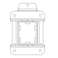
Mounting the detector directly
Fit the back-box of the detector onto the wall
by inserting the three M6 bolts, studs or
screws into the mounting holes.
Mounting the detector using the
bracket
A bracket (stainless steel) is available to mount
the detector that provides flexible adjustment to
easily position the detector to cover the pro-
tected area.
The surface chosen for the mounting should be
flat over the area of the mounting bracket to
ensure a stable fixing.
The FV400 Series of detectors can be operated
in any position but the mounting point must be
chosen to allow sufficient clearance for adjust-
Reference Document
Refer to the FV400 Series Product Infor-
mation and Design Application guide for
information on the Technical, Mechani-
cal, Electrical and Environmental specifi-
cations.
CAUTION
Do not open the detector when it is
powered; in hazardous areas or
environmentally challenging conditions.
Fig. 1: Detector Orientation Relative to Horizon
CENTRE OF DETECTOR
FIELD OF VIEW
PREFERRED METHOD