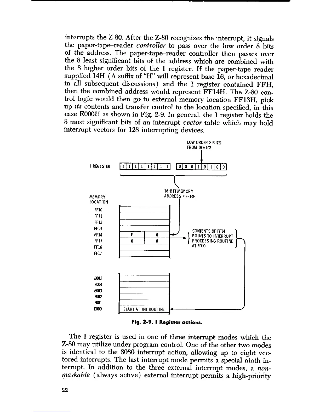
interrupts the Z-80. After the Z-80 recognizes the interrupt, it signals
the paper-tape-reader
controller
to pass over the low order 8 bits
of the address. The paper-tape-reader controller then passes over
the 8 least significant bits of the address which are combined with
the 8 higher order bits of the I register. If the paper-tape reader
supplied 14H (A suffix of "H" will represent base 16, or hexadecimal
in all subsequent discussions) and the I register contained FFH,
then the combined address would represent FF14H. The Z-80 con-
trol logic would then go to external memory location FF13H, pick
up
its
contents and transfer control to the location specified, in this
case E000H as shown in Fig. 2-9. In general, the I register holds the
8 most significant bits of an interrupt
vector
table which may hold
interrupt vectors for 128 interrupting devices.
LOW ORDER 8 B ITS
FROM DEVICE
I REGISTER
1
1 1 1 1 1 1 1 1
L
MEMORY
LOCATION
FF10
FF11
FF12
FF13
FF14
FF15
FF16
FF17
E005
E004
E003
E002
E001
E000
E
0
16-BITMEMORY
ADDRESS -FF14H
0
0
CONTENTS OF FF14
POINTS TO
INTERRUPT
PROCESSING
ROUTINE
AT E000
1
START AT
INT ROUTINE
Fig. 2-9. I Register actions.
The I register is used in one of three interrupt modes which the
Z-80 may utilize under program control. One of the other two modes
is identical to the 8080 interrupt action, allowing up to eight vec-
tored interrupts. The last interrupt mode permits a special ninth in-
terrupt. In addition to the three external interrupt modes,
a non-
maskable
(always active) external interrupt permits a high-priority
22
 Loading...