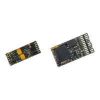
Non-Sound Decoder MX600 - MX638 and Sound Decoder MX640 - MX659 Page 35
Automatic disengage-
ment after uncoupling
=
“Automatic uncoupling”
Tens digit (0 – 9): Length of time the loco should move
away (disengage) from the train; coding as in CV
#115.
Ones digit (0 – 9) x 4 = Internal speed step applied for
disengagement (Momentum per CV #3 etc.)
Hundredths digit = 0: No unloading.
= 1: Coupler unloading: engine
moves toward train in order to relieve coupler tension,
before uncoupling and disengaging from the train.
Example:
CV #115 = 61: Loco uncouples and drives away from
train for 2 seconds at speed step 4.
CV #116 = 155: Loco pushes against train first to un-
load couplers, uncouples and then drives away from
the train for 1 second at speed step 20.
Notes to automated uncoupling with coupler-unloading and train disengagement
- The automatic train disengagement is active if the tens digit in CV #116 is other than 0; if desired with prior coupler
unloading (when CV #116 > 100).
- The automatic train disengagement (or the preceding coupler unloading) is started at the same time the coupler is
activated, but only if the train is standing still (speed 0); if the train is still moving, the uncoupling, unloading and
disengagement procedure won’t start until the train comes to a full stop.
- The procedure terminates when the “temporary” function key is released (or pressed again if in latched mode), or
when the predetermined times (CV #115 for the coupler, CV #116 for the disengagement) have expired.
- The uncoupling and disengagement process is aborted immediately if the speed regulator is operated at the same
time.
- The driving direction for the train disengagement is always according to the cab setting; directional settings in the
“special effects” definition for uncoupling (Bits 0 and 1 of CV #127, CV #128 etc.) will not be applied.
3.25 SUSI-Interface and Logic-Level Outputs (NOT for MX621)
All decoders described in this manual (except MX621) have outputs that can either be used as a SU-
SI interface, as logic level outputs or for servo control. These outputs are available at solder pads or
on the decoder plug (MTC or PluX), see the various decoder pin-outs starting on page 5.
These outputs are active as SUSI interface by default. To switch them to logic level outputs, config-
ure CV #124 as follows:
CV #124 = 128 or +128 (= Bit 7 in addition to other possibly set bits).
These logic level outputs are then always regarded as the next "normal" outputs. For example: The
MX630 comes with a total of 6 function outputs (Lfor, Lrev, FO1 – FO4). The two logic level outputs
are controlled as FO5 and FO6.
If these outputs are needed for servo control, leave CV #124, Bit 7 = 0 and define CV’s #181 and 182
instead (see next chapter “Servo configuration).
Shunting key
functions:
Changing SUSI
outputs
Bits 0 - 4, 6: Shunting key selection and
HALF-SPEED ACTIVATON
Bit 5 = 1: “ DC stopping”
Bit 7 = 0: SUSI is active (or as servo outputs if defined
as such in CV’s #181 and 182).
= 1: Logic level function outputs instead of SUSI
Bit 2 = 1: I²C an SUSI-Interface. This is an OEM feature.
For more details contact www.zimo.at
3.26 Servo Configuration (NOT for MX621)
Servo outputs:
Protocol
and alternative
use of
servo outputs 3 & 4
as SUSI
NOT for MX621
0 - 3
0
Note:
CV #161
must be
set to “2”
for
Smart
Servo
RC-1!
Bit 0 = 0: Servo protocol with positive pulses.
= 1: Servo protocol with negative pulses.
Bit 1 = 0: Control wire only active during movement
= 1: … always active (consumes power, vibrates
at times but holds position even under
mechanical load) – this setting is also required
for SmartServo RC-1 (with memory wire)!
Bit 2 = 0: For two-key operation, with center position (as
per CV #181/182) when both function keys
are OFF.
= 1: For two-key operation (as per CV #181/182),
where the servo runs only as long as function
keys are active.
Bit 3 = 1: Servo outputs 3 and 4 are used for SUSI Data
and SUSI clock (only for decoders that actually
have 4 servo outputs).
Defines the servo’s left stop position. “Left” may become
the right stop, depending on values used.
Defines the servo’s right stop position.
Defines a center position, if three positions are used.
Rotating speed; Time between defined end stops in
tenths of a second (total range of 25 sec, default 3 sec.).
#166
- 169
#170
- 173
#174
- 177
As above but for
Servo 2
Servo 3
Servo 4
#166 left stop, #167 right stop, #168 center position, #169 rotating speed.
#170 left stop, #171 right stop, #172 center position, #173 rotating speed.
#174 left stop, #175 right stop, #176 center position, #177 rotating speed.
= 0: Servo not in operation