Do you have a question about the ZKTeco BioPro SA20 and is the answer not in the manual?
Follow guidelines for installation, handling, and maintenance to ensure safety and prevent damage.
Maintain device cleanliness and contact support for any operational issues.
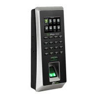
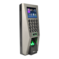
Identifies key components of the device, including display, keypad, sensors, and ports.
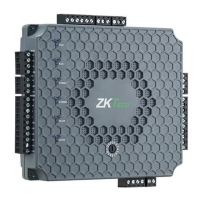
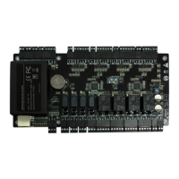
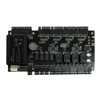
Details the pin configurations and functions for various device connectors and ports.
Provides physical dimensions of the device in inches and millimeters.
Step-by-step instructions for securely mounting the device to a wall.
Illustrates how to connect the device to a power source, with or without a UPS.
Specifies the required voltage and current ratings for the power supply.
Details the process of connecting the device to a local area network via Ethernet.
Illustrates the wiring for connecting the device to a PC via RS485.
Provides critical advice for optimal RS485 communication, including cable type and configuration.
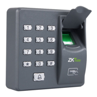
Details the RS485 wiring specific to the FR1200 fingerprint reader.
Explains how to configure RS485 settings through the device's system menu.
Describes the function of DIP switches for RS485 address and noise reduction.
Details wiring for a lock when the device does not provide power to it.
Important notes on supporting NO/NC locks and using a protection diode.
Details wiring for a lock when the device provides power to it.
Shows the pin connections and wire colors for Wiegand output.
Illustrates a typical standalone system setup with various components.
Interface for setting and configuring the device's date and time.
Instructions for adding new users, including fingerprint and badge registration.
Configuration interface for network settings like IP address and subnet mask.
Options for configuring access control parameters, time zones, and groups.
Troubleshooting steps for when the fingerprint sensor is not reading correctly.
Resolving issues where fingerprint verification fails authorization.
Troubleshooting why the door remains locked after successful verification.
Addressing 'system broken' messages and active alarms, often related to tampering.
| Model | BioPro SA20 |
|---|---|
| Device Type | IP Access Controller |
| Fingerprint Capacity | 3, 000 |
| Card Capacity | 10, 000 |
| Transaction Capacity | 100, 000 |
| Power Consumption | ≤ 5W |
| Operating Temperature | 0°C to 45°C |
| Operating Humidity | 20% to 80% |
| Software | ZKAccess3.5 |
| Max User Capacity | 10000 |
| Max Event Log Capacity | 100000 |
| Communication | TCP/IP |
| Access Control Interface | 3rd Party Electric Lock, Door Sensor, Exit Button |
| Wiegand Signal | Wiegand Output |
| Operating Voltage | DC 12V |
| Display | 2.4-inch TFT LCD |