Do you have a question about the ZLG USBCAN-4E-U and is the answer not in the manual?
Provides a general introduction to the USBCAN-4E-U high-performance CAN interface card.
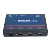
Details the physical appearance and components of the USBCAN-4E-U interface card.
Lists the key technical specifications and features of the USBCAN-4E-U interface card.
Details the electrical characteristics, voltage, and current ratings of the interface card.
Specifies the ambient and storage temperature ranges for the USBCAN-4E-U.
Outlines the protection grade test results and standards for the interface card's interfaces.
Describes the common application fields for the USBCAN-4E-U CAN interface card.
Explains the external and USB bus power supply options for the USBCAN-4E-U, including indicator behavior.
Details how to connect an external power supply to the USBCAN-4E-U.
Explains the USB bus power supply method and indicator status.
Details the function and usage of the DIP switch for setting CAN bus terminal resistance.
Describes the physical CAN-bus connectors and the pin definition for the DB9 interface.
Provides the signal mapping and pinout for the DB9 to OPEN5 connector conversion.
Explains the PWR, SYS, and CAN indicators and how they signify device status.
Details the specific functions and states of the PWR, SYS, and CAN indicators on the USBCAN-4E-U.
Guides on connecting the USBCAN-4E-U to a CAN-bus network and PC.
Details the physical connection procedure for the USBCAN-4E-U on a CAN-bus network.
Explains the importance of terminal resistance for CAN-bus reliability and its calculation.
Describes the methods and considerations for connecting the USBCAN-4E-U to a PC via USB.
Step-by-step guide for installing the USBCAN-4E-U driver on Windows XP and other systems.
Instructions for safely and completely uninstalling the USBCAN-4E-U device driver from the system.
Troubleshooting steps for the 'Fail to start the device' error in ZLGCANTEST.
Explains the necessity and application of 120 Ohm terminal resistance in CAN bus networking.
Addresses the possibility and limitations of installing multiple USBCAN-4E-U interface cards in one computer.
Details the maximum data conversion rate supported by the USBCAN-4E-U for CAN bus communication.
Explains the reasons behind the CAN state indicator turning off or behaving unexpectedly.
Troubleshooting illegal system operations encountered when calling interface functions.
Provides guidance on how to set the communication baud rate for the PC-CAN interface card.
Discusses how system standby or sleep modes affect CAN reception and the device's operation.
Methods for diagnosing and resolving function call and CAN-bus communication errors in applications.
Key considerations and procedures for safely turning the USBCAN-4E-U device on and off.
Explains how to utilize interrupt mode for operating the communication card effectively.
Tips and best practices for using the VCI_Transmit function for data transmission.
Provides guidance on optimizing the use of the VCI_Receive function for efficient data reception.
| Interface | USB 2.0 |
|---|---|
| CAN Channels | 4 |
| CAN Protocols Supported | CAN2.0A, CAN2.0B |
| Baud Rate | 5Kbps~1Mbps |
| CAN Controller | NXP SJA1000 |
| Isolation Voltage | 2500 Vrms |
| Storage Temperature | -40°C~+85°C |
| Power Supply | USB powered |
| Operating Voltage | 5V |
| Transceiver | NXP TJA1050 |
| LED Indicators | Power |
| Operating Temperature | -40°C~+85°C |