4
© Copyright 2013 Zoeller Co. All rights reserved.
OR
HYDRAULIC CEMENT
LEVEL WITH
OR SIMILAR MATERIAL
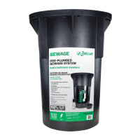
STEP 1 LOCATION SELECTION AND LEVELING OF TANK
Figure 1.1
NOTE: If a built in installation is to be used, locate pump chamber
in an area that will allow access to the pump & switch.
1.1) Select a location which is readily accessible to the existing
discharge and vent lines.
1.2) Level tank to within
1
/
8
” for length and width. Use hydraulic
cement or similar material for leveling. Refer to Figure 1.1.
Do not use wooden shims to level tank!
Ensure that nails, screws or other sharp objects do
not puncture tank!
STEP 2 ORIENTATION OF TOILET ON TANK
2.1) Determine the orientation of toilet on tank. This
determines the location of the long bolts in STEP 3 of
the installation. Refer to Figure 2.1 or Figure 2.2.
NOTE: Model 101 comes preassembled in the forward
installation position. If a side installation is desired, bolts must
rst be removed and then reinstalled per STEP 3. Also, if
subooring is being installed, the 2” bolts must be removed
and replaced with 3” bolts per STEP 3.
Side Installation
Figure 2.2
Forward Installation
Figure 2.1
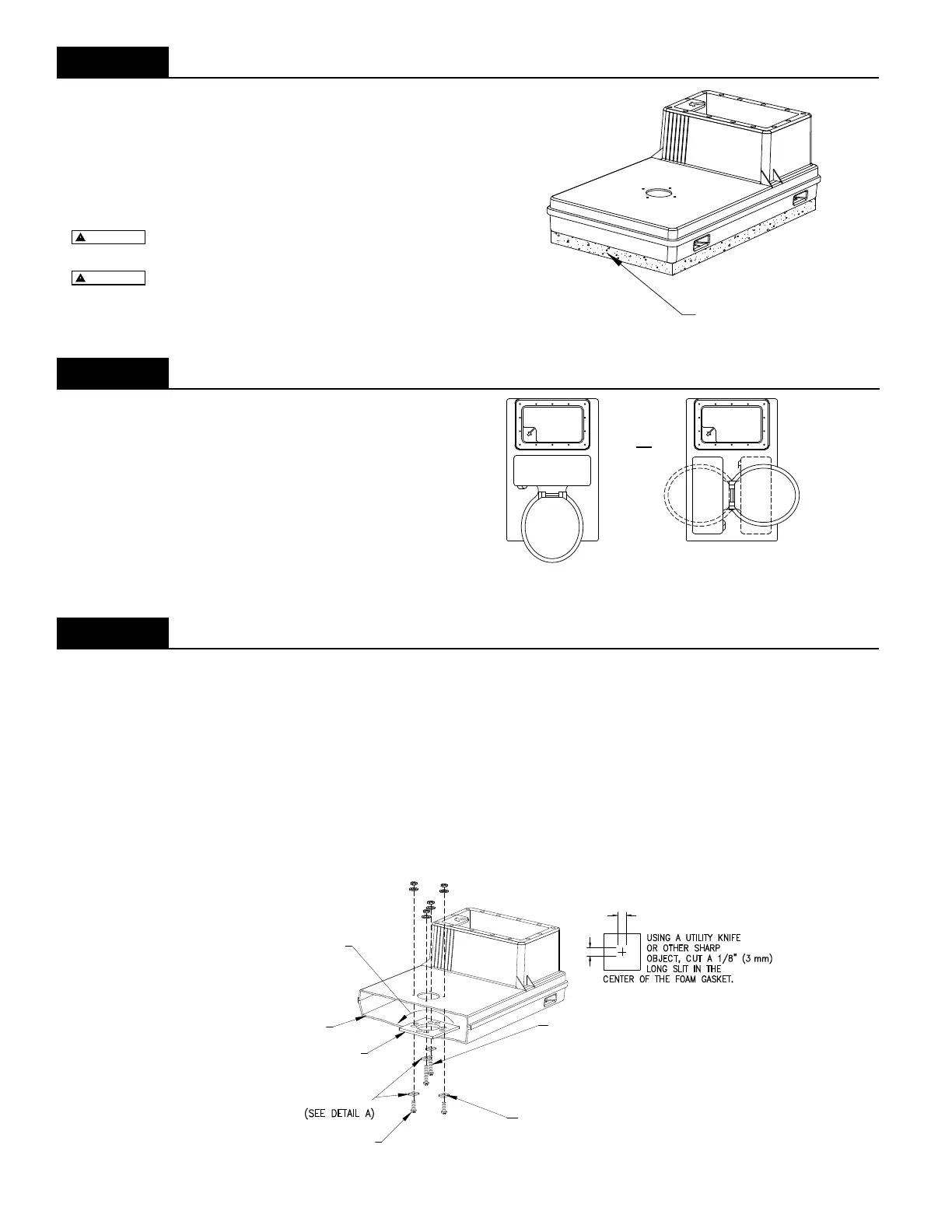
STEP 3 INSTALLATION OF THE CAST IRON SUPPORT
Model 101: If the bolts are correct for your desired installation, skip to STEP 6.
NOTE: If subooring is being installed over the tank, use the ¼” - 20 X 3” long bolts supplied with the oor
ange extender kit, otherwise use the ¼” - 20 X 2” long bolts. The longer bolts account for the thickness of
the subooring when mounting toilet.
3.1) Drill the 4 preselected holes, located around the toilet opening, with a
9
/
32
” drill bit. (Models 100 & 102 only)
3.2) Modify the 4 foam gaskets, supplied with the wax ring kit, as shown in Detail “A”. (Models 100 & 102 only)
3.3) Install the cast iron plate inside the tank through the pump chamber with the at side up. Rotate the plate to rest
on tank supports. (Models 100 & 102 only)
3.4) Make certain that the 2” or 3” long toilet mounting bolts are in the correct locations to accept the toilet as deter-
mined in STEP 2. Torque screws to 25-30 in-lbs.
AND ADHERE GASKET TO UNDERSIDE
OF CAST IRON SUPPORT AT EACH
2 X (1/4-20 X 1" (25 mm))
BOLTS
HOLE LOCATION.
REMOVE PROTECTIVE BACKING
SUPPORT FLANGE
(SEE DETAIL A)
FOAM GASKETS
CAST IRON
CUT-AWAY
OF TANK
LONG SLIT IN THE
CENTER OF THE FOAM GASKET.
2 X (1/4-20 X 3" (75 mm)) BOLTS
2 X (1/4-20 X 2" (50 mm)) OR
SEE NOTE:
USING A UTILITY KNIFE
OR OTHER SHARP
OBJECT, CUT A 1/8" (3 mm)
1/8” (3 mm)
1/8” (3 mm)
ON TANK SUPPORTS
ROTATE PLATE TO REST
DETAIL “A”
SK1746
SK1747
Figure 3.1
SK1748
 Loading...