Chapter3StructureandPrinciple
Panel
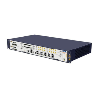
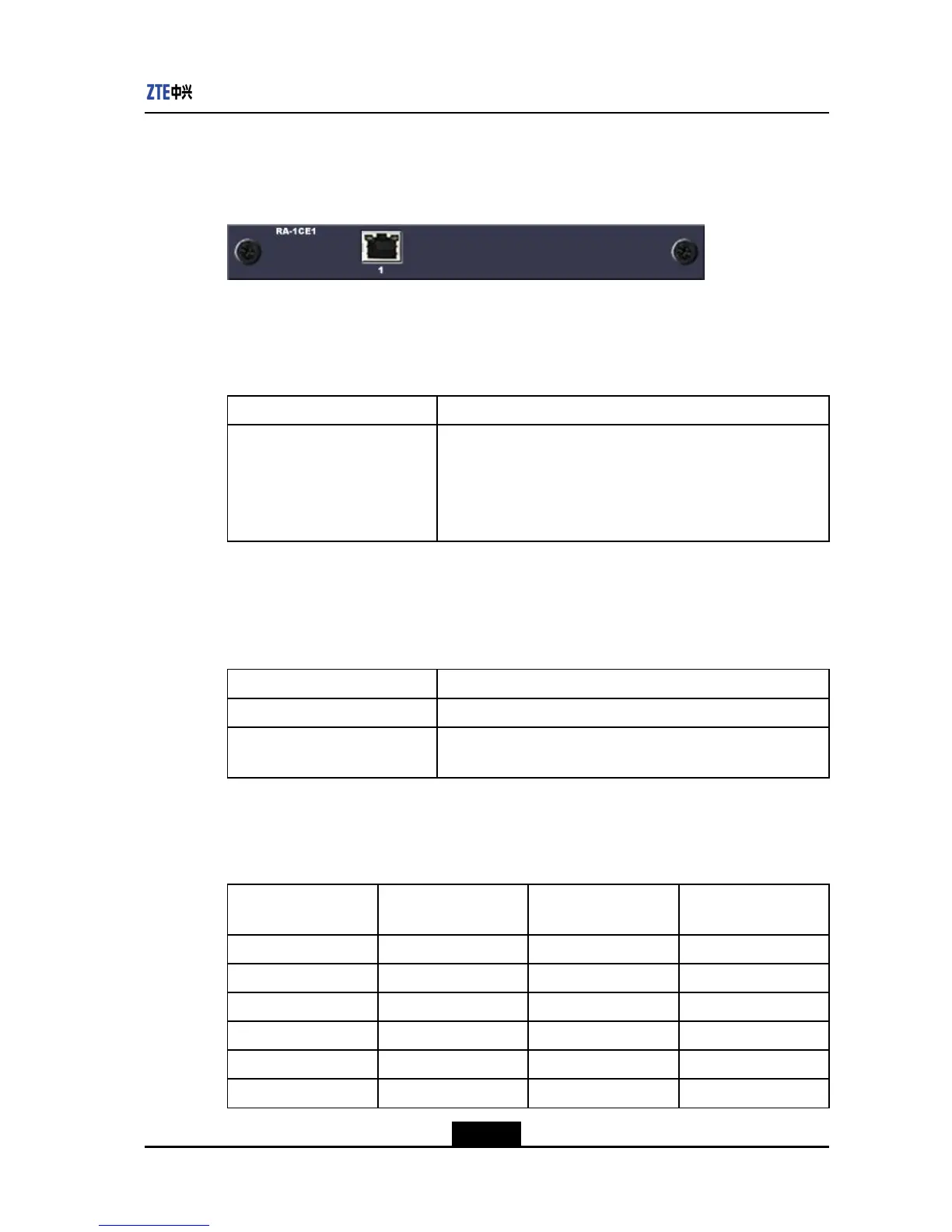
PanelofRA-1CE1boardisshowninFigure3-7.
Figure3-7RA-1CE1BOARDPANEL
Interface
FeaturesofinterfaceonRA-1CE1boardareshowninT able3-14.
Table3-14FEATURESOFINTERFACESONRA-1CE1BOARD
PortTypeSpecications
ChannelizedE1
IncompliancewithITU-TG.703andG.704Recommendations
SupportingG.704framing
RJ48connectorand120Ωtwistedpair
LinecodeofHDB3
AchannelizedE1controllerhas31validtimeslots
Indicators
TherearetwoindicatorsonthetopofinterfacesonRA-1CE1board.Theirfunctionsare
listedinT able3-15.
Table3-15DESCRIPTIONOFINDICATORSONTHERA-1CE1BOARD
IndicatorFunctions
Leftindicator(Yellow)Alarmindicator:Onindicatesport/linefault
Rightindicator(green)Linestatusindicator:Onindicatesthelineandlinesignalsare
normal
Interconnection
Table3-16showstheinterconnectionmethodofRJ48connectorsonE1interface.
Table3-16INTERCONNECTIONOFRJ48CONNECTORSATE1PORT
RJ48ofGARCE1
BoardSignal
E1RJ48Connectorof
MatingDeviceSignal
1RX_RING4TX_RING
2RX_TIP5TX_TIP
3Notconnected3Notconnected
4TX_RING1RX_RING
5TX_TIP2RX_TIP
6Notconnected6Notconnected
3-13
SJ-20110803091932-001|2011-12-15(R2.0)ZTEProprietaryandCondential
 Loading...