247Security Inc. | 4400 North Point Parkway, Suite # 158, Alpharetta, GA 30022, USA | 1-866-693-7492 | www.247securityinc.com
mDVR303
USERS MANUAL
12
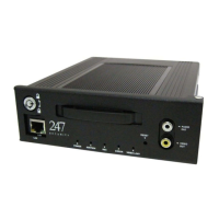
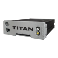
2.2.2. CAMERA 1-3 CONNECTORS
The mDVR303 supports a maximum of 3 cameras. These Micro-fit connectors are used to connect the
camera inputs to the mDVR303 system (video and audio) using a gang plug adapter for the cameras. Also
included in each camera connection is DV12V Out to power the camera. You can refer to the cover of the DVR for
the PIN assignments of each connector. If any of these cameras are not connected properly (for instance loose
cables, unplugged etc…) than the mDVR303 intelligently notifies the end-users with “NO VIDEO” on the preview
screen. Camera inputs are labeled CAMERA 1, CAMERA 2 and CAMERA 3
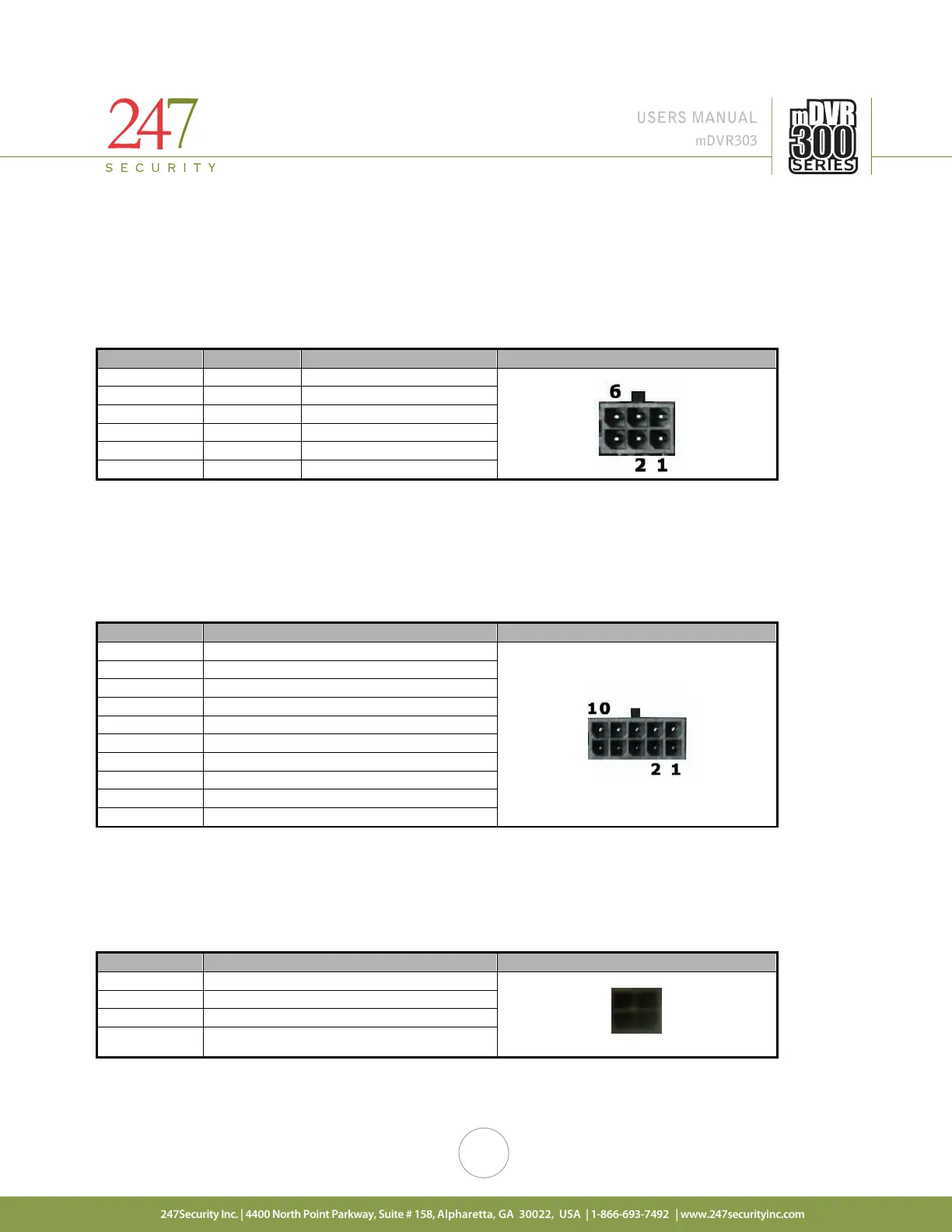
2.2.3. GENERAL PURPOSE INPUT / OUTPUT CONNECTOR #1
This connector provides 5 digital inputs and 1 digital output. The digital inputs are labeled as DI_1, DI_2,
DI_3, DI_4, DI_5. The digital output is labeled as DO_3. End-users can assign any sensors to one of these digital
input signals. Up to 5 sensors can be wired to this connector. Alternatively, one alarm (LED, Siren, etc.) is available
on the digital output.
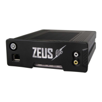
2.2.4. GENERAL PURPOSE INPUT / OUTPUT CONNECTOR #2
This connector provides 3 digital inputs. The digital inputs are labeled as DI_6, DI_7, DI_8. End-users can
assign any sensors to one of these digital input signals, up to 3 sensors can be wired to this connector. This
connector also provides +12VDC OUT on pin 4 with a built-in 0.75A fuse.
2 1
4 +12VDC OUT