10 CHAPTER 1: INTRODUCING THE BASELINE SWITCH
Entweder geschützte oder ungeschützte Buchsen
dürfen an diese Datensteckdosen angeschlossen wer-
den.
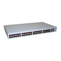
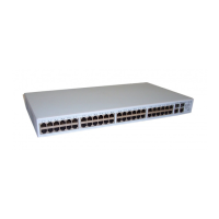
The Switch has 48 10/100 Mbps autonegotiating
ports (ports 1 to 48). Their speed and duplex mode
(half-duplex or full-duplex) are automatically deter-
mined by the capabilities of the connected device.
Each port also supports automatic MDI/MDI-X detec-
tion and can be connected to either a 10BASE-T, or a
100BASE-TX device.
CAUTION: The Switch supports full-duplex autone-
gotiation. If the connected device does not support
autonegotiation, the Switch will operate in
half-duplex mode (even if the attached device is oper-
ating in full-duplex mode).
In such a configuration, you may notice some
degradation of network performance. 3Com
recommends that you use devices that are capable of
autonegotiation (and that you ensure that
autonegotiation is enabled, if it is a configurable
option). (see “
Troubleshooting” on page 43).
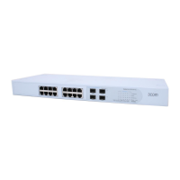
(2) 10/100/1000BASE-T/SFP Ports
Ports 49 and 50 are combination Gigabit RJ-45 ports
with shared Small Form Factor Pluggable (SFP) trans-
ceiver slots. If an SFP transceiver (purchased sepa-
rately) is installed in a slot and is active, the associated
RJ-45 port of the same number is disabled.
The 1000BASE-T RJ-45 ports support automatic
MDI/MDI-X operation, so you can use
straight-through or crossover cables for all network
connections to workstations or servers, or to other
switches or hubs.
The two SFP ports support fiber Gigabit Ethernet
short-wave (SX) and long-wave (LX) SFP transceivers
in any combination. This offers you the flexibility of
using SFP transceivers to provide connectivity
between the Switch and remote 1000 Mbps work-
groups or to create a high-capacity aggregated link
backbone connection.
SFP ports are numbered 49 and 50 on the Switch.
When an SFP port is active, it has priority over the
10/100/1000 port of the same number. The corre-
sponding 10/100/1000 port is disabled when an SFP
transceiver is plugged in.
(3) Link/Activity LEDs
The following tables describe the LEDs visible on the
front of the Switch, and how to read their status
according to color.
Tab le 4 10BASE-T/100BASE-TX Ports
Status Meaning
Green Link established, operating at 100 Mbps
Yellow Link established, operating at 10 Mbps
 Loading...