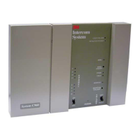
I/O Board and Noise Reduction Module
Installation
Performance Series
2
I/O Card and Noise Reduction Module Installation
I/O Card Installation
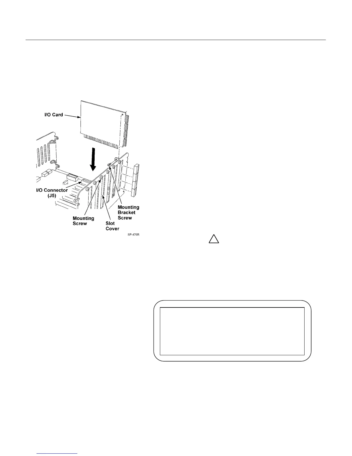
Figure 2. I/O Card Installation
Be sure the system is powered off!
1. Remove 4 screws on each side of the Communications
Controller cover.
2. Remove cover.
Note: Insert I/O cards beginning from connector J5. Add
additional I/O cards sequentially (J6, J7, etc.).
3. Remove slot cover and mounting screw. Refer to Figure 2.
4. Remove all terminal blocks from edge of I/O card.
5. Insert I/O card into I/O connector by pressing gently into
place.
6. Use slot cover mounting screw to secure I/O card to
chassis.
7. Insert terminal blocks into I/O card station ports.
8. Repeat until all I/O cards are installed.
9. Replace cover and 8 screws.
!
Important
A larger power supply must be used if more than four (4).
I/O cards are installed. Use D2470-20 power supply Part
Number 78-8117-4153-3 when more than four (4) I/O cards
are installed.
After the larger power supply is installed, Remove the
following Warning label:
Note
If adding additional I/O cards after initial installation, you must re-
program parameter 03, “max stations.”
WARNING
Do not add any I/O cards to these slots
unless power supply output rating exceeds 4
Amps. See installation instructions for
details.