Do you have a question about the 3M 701 and is the answer not in the manual?
Required electrometer or equivalent with specified input impedance for testing.
Decade box or individual resistors (100kΩ to 10GΩ) for calibration and verification.
Figures illustrating calibration adjustments and PC board assemblies.
Set selector to OFF and adjust mechanical zero to the left end of the scale.
Check pointer in the green area of the BATTERY TEST scale.
Verify 100kΩ resistor reading and full-scale deflection with a short.
Verify 10GΩ and 1MΩ readings in 10V and 100V SURFACE TEST modes.
Verify Keithley 619 output is 93V-107V in 100V SURFACE TEST mode.
Install batteries and set selector to BATTERY TEST position.
Adjust R10 for 10.00V ± 0.01V between U2 Pin 7 and ground.
Adjust R23 for 100.0V ± 0.1V between SW1 Pin 12 and ground.
Adjust R21 for full-scale pointer reading in 100V SURFACE TEST mode.
Adjust R36 (or R8 for Issue 1) for 100V mark on BATTERY TEST scale.
Verify resistance readings (100kΩ-10GΩ) in 10V and 100V SURFACE TEST modes.
Confirm proper readings with short and 100kΩ in CONTINUITY TEST mode.
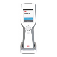
The 3M 701 Megohmmeter is a specialized instrument designed for measuring high electrical resistance, primarily used in applications requiring surface resistance testing. Its core function is to provide accurate resistance measurements across a wide range, from kilohms to gigaohms, which is crucial for evaluating materials and components in various industries.
The device is designed for ease of use, featuring a selector switch that allows users to choose between different operational modes. These modes include an "OFF" position for safe handling and storage, a "BATTERY TEST" mode to ensure the internal power source is adequate for measurements, and "CONTINUITY TEST" for checking basic circuit integrity. For resistance measurements, it offers "10V SURFACE TEST" and "100V SURFACE TEST" modes, providing flexibility depending on the required test voltage and the nature of the material being tested.
A key feature of the 3M 701 Megohmmeter is its analog meter display, which provides a visual indication of resistance values. The meter scales are nonlinear, meaning the spacing between marks changes across the range to accommodate the broad measurement capability. The "A" scale on the meter identifies midpoints between major resistance ranges, while the "B" scale provides finer divisions for specific ranges: 50K per mark from 0 to 100K, 100K per mark from 100K to 1.0M, 1M per mark from 1.0M to 10M, 20M per mark from 10M to 100M, 200M per mark from 100M to 1.0G, and 2.0G per mark from 1.0G to 10G. This detailed scaling allows for precise readings within each range.
For accurate measurements, the device incorporates a mechanical zero adjustment, which allows users to set the pointer to the left end of the scale when the unit is off, ensuring a proper starting point for all readings. The battery test function is particularly useful, as it allows users to quickly verify that the internal battery voltage is within the acceptable "green (100V)" area, ensuring reliable operation before conducting critical tests.
The verification procedure for the 3M 701 Megohmmeter involves several steps to confirm its performance. This includes placing known resistance values across the input and checking if the meter readings fall within specified tolerances. For instance, in "CONTINUITY TEST" mode, a 100KΩ resistor should yield a reading within ±2° of the 100KΩ mark, and a short circuit should result in full-scale deflection. In "SURFACE TEST" modes, the device is checked against a decade box or individual resistors across a wide range (e.g., 1MΩ to 10GΩ) to ensure accuracy. The output voltage in the "100V SURFACE TEST" mode is also verified to be within a specific range (93V to 107V) using an external electrometer.
Maintenance and calibration are integral to ensuring the long-term accuracy and reliability of the 3M 701 Megohmmeter. The calibration procedure outlines specific adjustments that can be made if the device does not meet performance specifications during verification. These adjustments involve internal potentiometers (R10, R23, R21, R36, and R8 for Issue 1 PC Boards) that fine-tune various aspects of the device's operation. For example, R10 adjusts the voltage between U2 Pin 7 and ground to 10.00V, R23 adjusts the voltage between SW 1 Pin 12 and ground to 100.0V, and R21 adjusts the full-scale deflection in "100V SURFACE TEST" mode when the input is shorted. R36 (or R8 for Issue 1 PC Boards) is used to align the pointer with the 100V mark on the "BATTERY TEST" scale.
The device's internal components are laid out on a printed circuit board (PCB), with different issues of the board (Issue 1, Issue 2, Issue 3) indicating potential minor revisions or improvements over time. These PCBs contain various resistors, capacitors, diodes, and integrated circuits that work together to perform the resistance measurements and display the results. The calibration adjustments are clearly identified on diagrams of the PCB, facilitating precise tuning by trained personnel.
The accuracy of the 701 Megohmmeter is defined by two tolerances: a +/- 5% electrical tolerance and a +/- 2-degree tolerance for the meter's needle movement. These combined tolerances are visually represented by small dots on either side of the major resistance marks on the meter's top scale. During verification, readings are expected to fall within these dots, confirming the device's measurement accuracy. This method of indicating tolerance directly on the meter scale provides a clear visual guide for users to assess the validity of their measurements.
Overall, the 3M 701 Megohmmeter is a robust and precise tool for resistance measurement, designed with both operational functionality and long-term maintainability in mind. Its detailed calibration and verification procedures ensure that it consistently delivers accurate results, making it a valuable instrument for quality control and material evaluation.
| Category | Measuring Instruments |
|---|---|
| Accuracy | ±5% |
| Display | LCD |
| Battery | 9V battery |
| Operating Temperature | 0°C to 50°C |
| Storage Temperature | -20°C to 60°C |