6 / 11
MO 0765-0601
1
5
6
4
3
2
1
5
6
4
3
2
Output
connector
Output
connector
Computer
input
Computer
ground
External
voltage
source
max. 30 V
Pin 3
+ 5V
5 kΩ
Pin 1, 2, 4 or 5
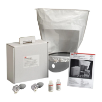
Pin 6
Relay
I max. 20 mA
Pin 1, 2, 4 or 5
Pin 6
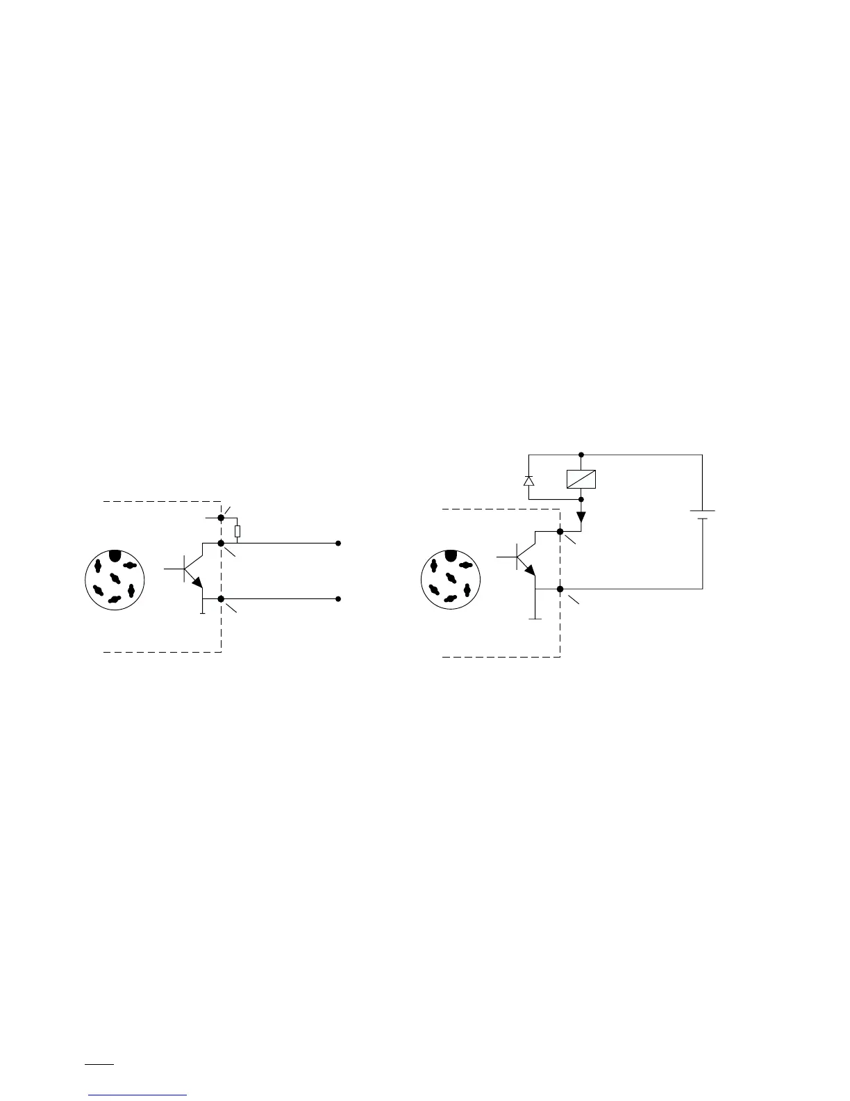
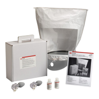
VIII. Data Output Connector
If you are going to use the data output connector you must follow a test sequence. It must be wrist strap
test first and then the shoe test. If this sequence is not strictly kept, the output at the pins described
on page 7 will be altered.
The 740 will provide digital signals (high/low) while testing the personnel grounding devices. These
digital signals can be used for data recording (Example 1) and authorization control equipment such as
electrical door opening systems (Example 2). The output of the 740 will give you permanently +5 V at
pin 3 and DC-return at pin 6. The remaining pins 1, 2, 4 and 5 (open collector) will be high (max. +30
V / 20 mA have to be provided externally) or low (DC-return) while pressing on the contact plates
either for wrist strap or shoe tests. The chart on page 7 shows all of the possible test results and the
corresponding output levels.
Example 1: Output connection for use
with a computer
Example 2: Output connection for use
with a controlling device