8 / 11
MO 0765-0601
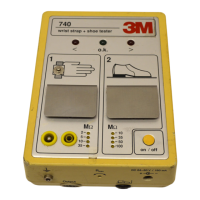
740
wrist strap + shoe tester
3
<
>
o.k.
12
2 -
5 -
10 -
35 -
- 10
- 35
- 50
- 100
on / off
+
-
Output
R
max
DC 24
•
30 V / 150 mA
750 kΩ
AB
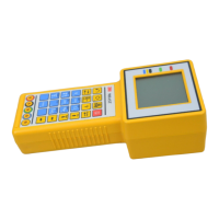
X. Verification Procedure
The following procedure can be used to determine
if the 740 operates within its specifications.
Please note: The tester has no adjustable
components.
Equipment needed:
1. resistors -
750 kΩ - 120 MΩ, tolerance ± 1%
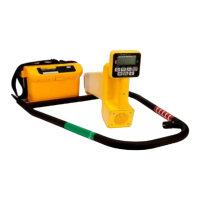
2. 2 wires
as required to connect the reference resistor
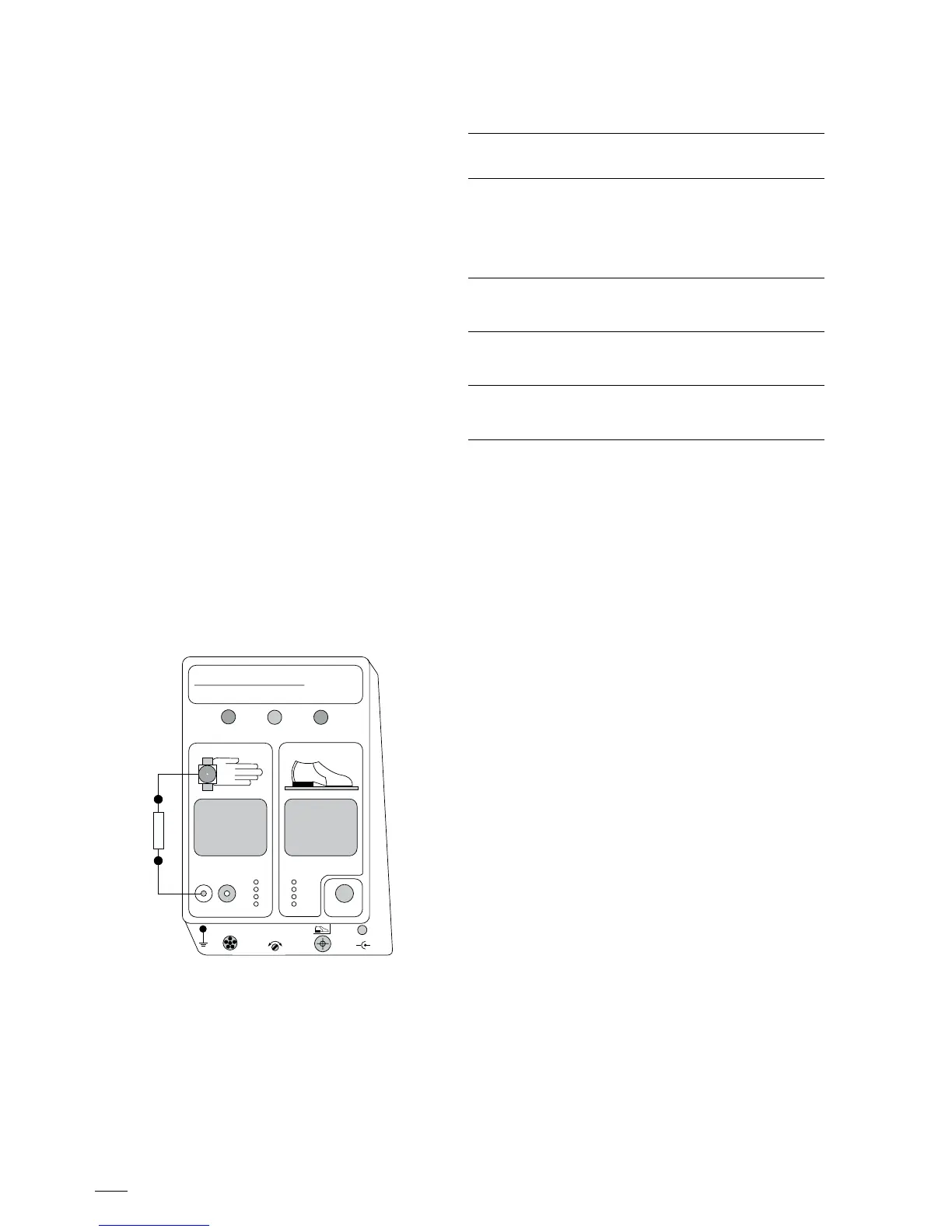
Verification of wrist strap test circuit:
Connect the reference resistor to the 740 as shown
in the Figure 1. Switch the 740 unit on. Select the
2 MΩ range and use the reference resistors as
indicated in the test table and press contact
plate A.
The LEDs will indicate as shown below if the 740
performs within specifications. Repeat this
procedure for 5, 10 and 35 MΩ ranges.
Reference Resistance LED -
resistor range settings Indication
*750 kΩ 2 MΩ - range Red
900 kΩ Green
1.8 MΩ Green
>2.2 MΩ Red
4.5 MΩ 5 MΩ - range Green
>5.5 MΩ Red
9.0 MΩ 10 MΩ - range Green
>11.0 MΩ Red
31.5 MΩ 35 MΩ - range Green
>38.5 MΩ Red
*This example is used above
Figure 1