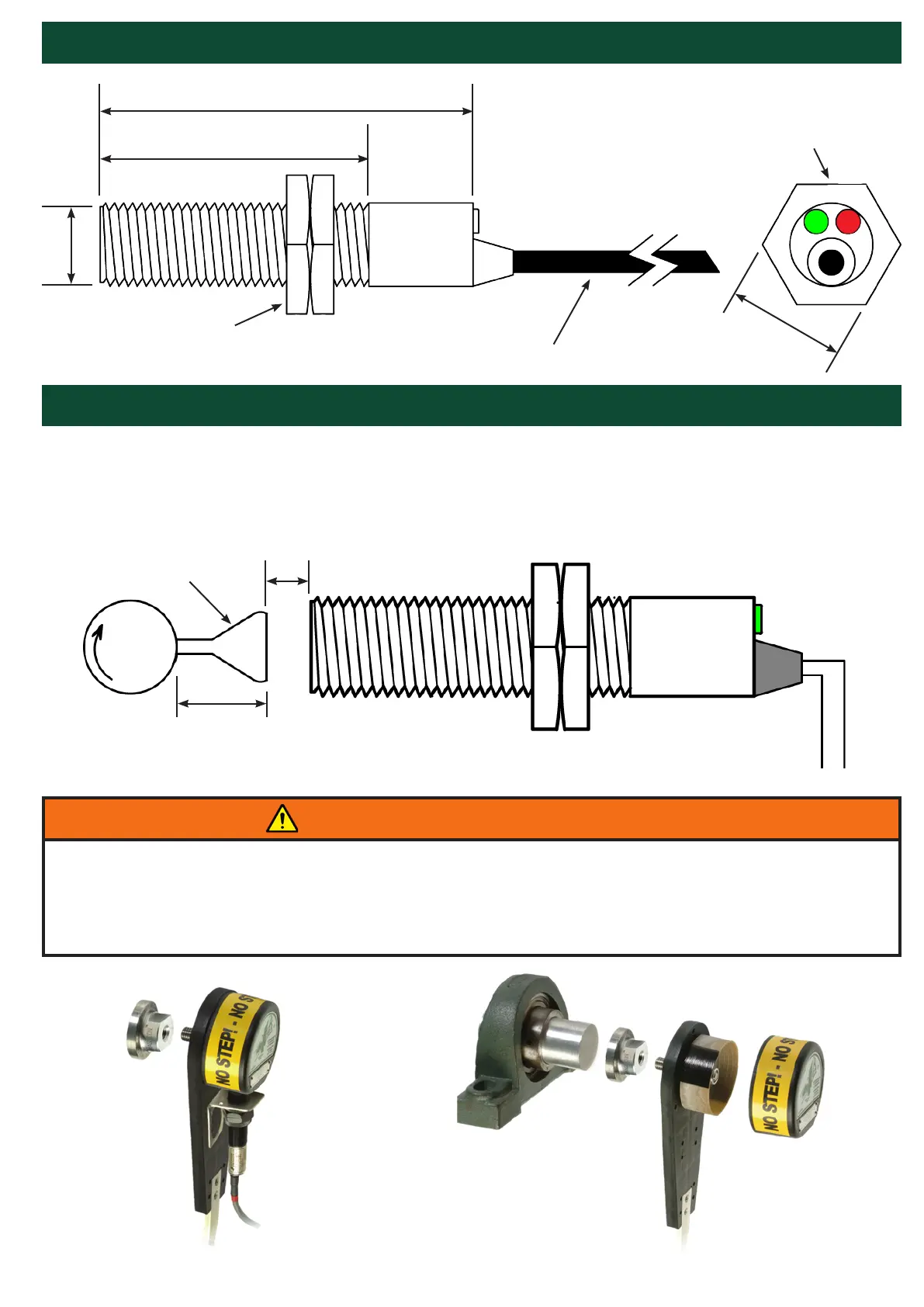
DIMENSIONS
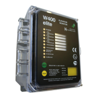
INSTALLATION
Fasten the M100 Stopswitch to a suitable mounting bracket with guard, such as 4B’s Whirligig®
universal shaft sensor mount, with the nose of the switch within the sensing range of the target, as
shown below -
PAGE 7
Shaft
3/4 in. Diameter
Ferrous Target
1/4 in.
(Min)
Ferrous Target - 5/16 in. (8 mm) Max.
Non-Ferrous Target - 3/16 in. (5 mm) Max.
3-1/8
2-1/4
1
11/16
ALL DIMENSIONS
IN INCHES
6 ft. Cable
2 x 20 AWG Conductors
Locknuts
Green LED (Output)
Red LED (Input)
WARNING AVERTISSEMENT
O.S.H.A. requires that all exposed rotating shafts are provided with a full guard. Therefore, this device
and its target must be equipped with a guard.
O.S.H.A. exige que tous les arbres rotatifs exposés soient dotés d’une protection complète. Par
conséquent, cet appareil et sa cible doit être équipée d’un garde.
M100 Stopswitch Shown on Optional
Whirligig® Shaft Sensor Mount/Guard
with Mag-Con™ Magnetic Connector