NOTE
Load refers to any item that limits current (PLC input, ice cube relay, etc.) that you would like the
M100 to switch on/off. Load must be the same voltage rating as the supply being used. Total circuit
current is 200 mA (max).
STANDARD WIRING DIAGRAM
All wiring must be In accordance with local and national electrical codes and should be undertaken
by an experienced and qualied electrician. All wiring methods must be suitable for ClassII Division1
(Groups E,F&G) Hazardous Locations.
Always use dust/liquid tight exible metal conduit with approved ttings to protect the sensor cables.
Use rigid metal conduit to protect the cables from the sensors to the control unit. Conduit systems can
channel water due to ingress and condensation directly to sensors and sensor connections which over
time will adversely affect the performance of the system. As such, the installation of low point conduit
drains is recommended for all sensors.
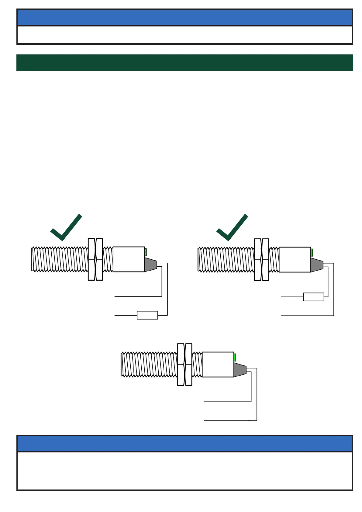
The M100 has a two wire cable. It must be wired through a load (see below) with the same voltage
rating as the supply being used. The supply polarity to the M100 is not important and the load can be
connected to either wire. The cable can be extended to virtually any length with ordinary 2 wire cable.
Do not wire the M100 directly to a motor starting coil due to the 200 mA maximum current capacity.
It is not recommended to wire the M100 in series with other sensors.
PAGE 8
Blue (L / +V)
Supply
24 to 240
Volts AC/DC
Black (N / 0V)
IN-CORRECT
x
NOTE
18 mm to 1/2 inch NPT Conduit Adapter Available (Part # A12NPT)
Blue (L / +V)
LOAD
Supply
24 to 240
Volts AC/DC
Black (N / 0V)
CORRECT
LOAD
Blue (L / +V)
Supply
24 to 240
Volts AC/DC
Black (N / 0V)
CORRECT