User’s Manual
Enterprise Access Point ENGLISH
14
Copyright © 4IPNET, INC.
EAP747 / EAP750 / EAP757
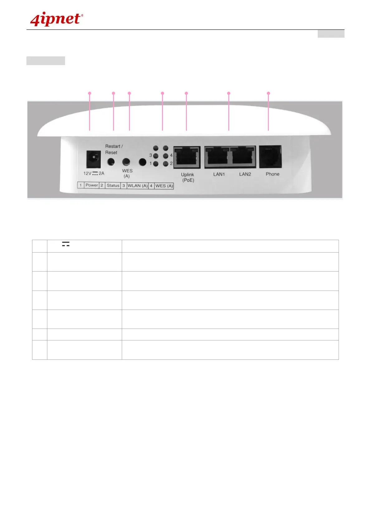
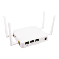
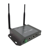
Rear Panel
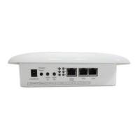
Figure 3 EAP747 / EAP750 / EAP757 Back Panel
Attach the power adaptor here.
Press once to restart the system; Press and hold for more than 5 seconds
to reset to factory default.
WDS Easy Setup. Press the button to build up a WDS link with another
peer.
4 LED lights. Representation is listed at the bottom of the panel. (Top 2
reserved for RF Card B if applicable)
For Uplink connection. This port can be used to connect to a controller,
gateway, or directly to the internet. PoE is supported.
Attach Ethernet cables here to connect to the wired local network.
A telephone can bypass to a connected phone line in the back of the AP
when connected to the socket.