Page 17
4 Block Diagram
The elements that make up an EtherSapceLink family unit are shown below.
5 User Interface
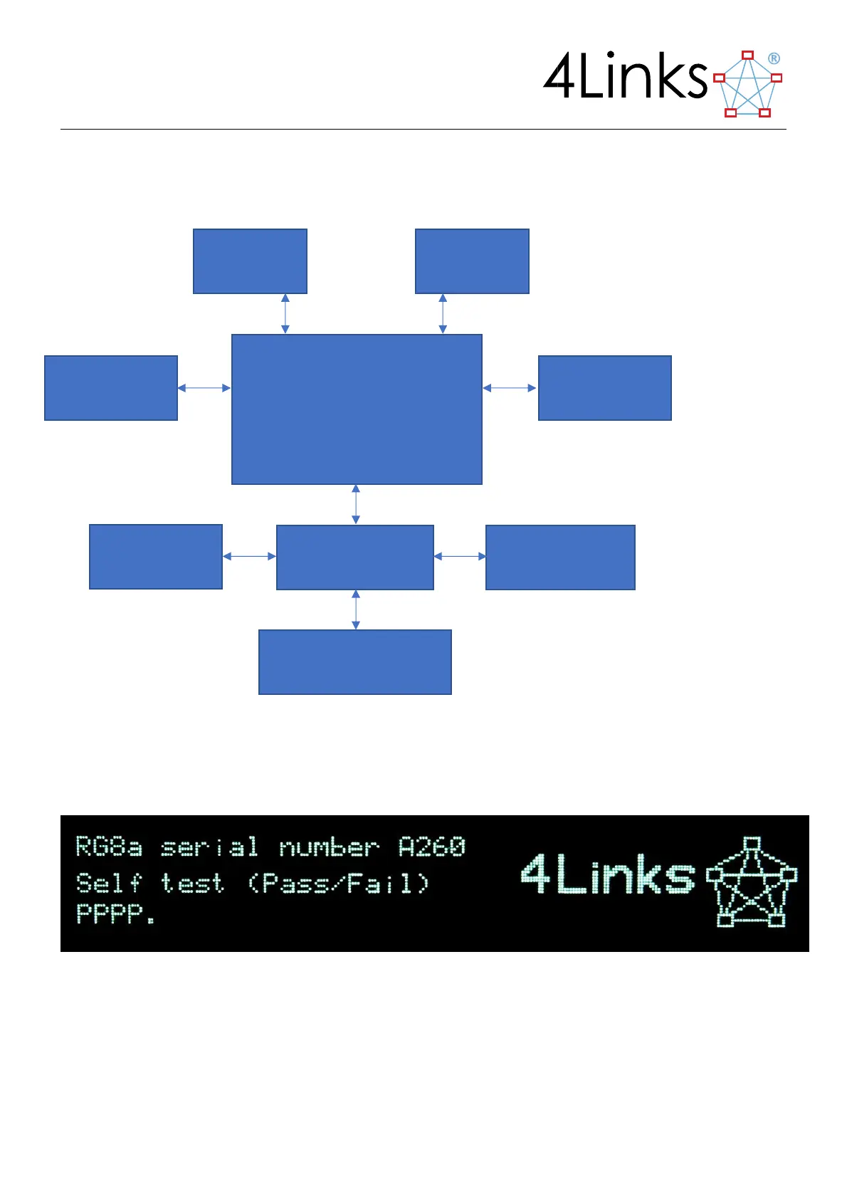
5.1 Initial (Power-up) display
The front-panel display will initially show the unit proceeding through self-test and configuration, leading after a
few seconds to a normal operational display.
FIGURE 5-1 THE RG408 POWER-UP DISPLAY
FPGA board, containing:
Ethernet TCP/IP interface
SpaceWire Link interfaces
Transmit and receive buffers
Power Supply
Synchronisation
SMA connectors
System Status
System Controller
Configuration data
CF Card
User Interface
Front panel display/switch