39
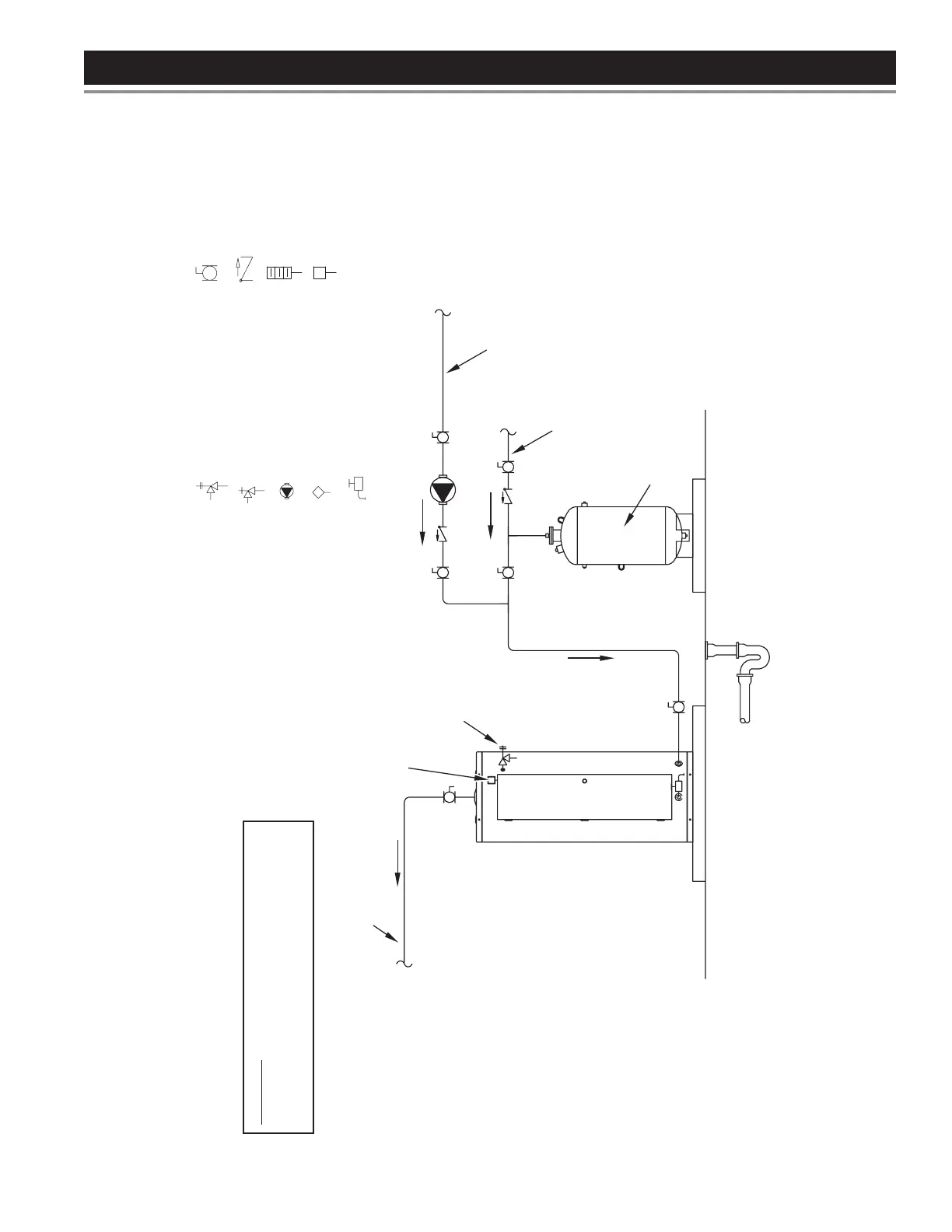
PIPING DIAGRAMS
October 2009 | Printed in U.S.A. | © A. O. Smith For Technical Information and Automated Fax Service, call 800-527-1953 or visit www.hotwater.com. AOSCE61010 | PAGE 1 of 1
A. O. Smith Corporation reserves the right to make product changes or improvements without prior notice.
NOTES:
1. Preferred piping diagram.
2. The temperature and pressure relief valve setting shall not exceed pressure rating of any component in the system.
3. Service valves are shown for servicing unit. However, local codes shall govern their usage.
COMMERCIAL ELECTRIC - (1 UNIT)
LEGEND
TEMPERATURE & PRESSURE
RELIEF VALVE
PRESSURE RELIEF VALVE
CIRCULATING PUMP
TANK TEMPERATURE CONTROL
DRAIN
FULL PORT BALL VALVE
TEMPERATURE GAGE
WATER FLOW SWITCH
CHECK VALVE
WARNING: THIS DRAWING SHOWS SUGGESTED
ATION AND OTHER DEVICES;
CODES AND ORDINANCES
FOR ADDITIONAL REQUIREMENTS.
FINISHED
FLOOR
HOT WATER
TO FIXTURES
FUSED
DISCONNECT
SWITCH
HOT WATER
RETURN
EXPANSION
TANK
COLD WATER
SUPPLY
PIPE T&P TO
OPEN DRAIN
Printed on 2/8/2018 9:05 AM CT