Do you have a question about the A.O. Smith BTH 199 and is the answer not in the manual?
Details the required skills and qualifications for performing service on the water heater.
Lists the necessary tools and equipment for proper installation and maintenance.
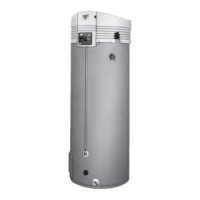
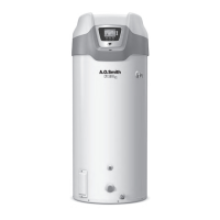
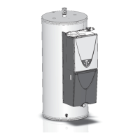
Overview of required clearances for direct vent units and specific model illustrations.
Recommended clearances for installations using horizontal venting.
Recommended clearances for installations using direct vent configurations.
Specifies the minimum air volume required per BTUH input for safe combustion.
Guidelines for make-up air openings in enclosed spaces and duct installations.
Details hazards of contaminated air and flammable materials near the heater.
Addresses condensate drainage, its pH level, and potential issues.
Table for equivalent feet of vent pipe based on length and elbows.
Details supply and manifold gas pressure requirements for various models.
Flowchart detailing the unit's operational sequence from power on to heating.
Lists expected panel lights and readings when the unit calls for heat.
Details control board connections, voltage readings, and indicator lights.
Covers pre-service checks, igniter, and gas valve coil continuity.
Tests AC voltage, transformer, ECO, and thermistor function.
Verifies blower operation, speed, and pressure switch functionality.
Tests igniter voltage supply and gas pressures for proper operation.
Lists part numbers and voltage for gas valves and Hot Surface Igniters.
Provides main burner orifice numbers and sizes for different BTH models.
Details the pressure points for blocked inlet/outlet and blower proving switches.
Schematics for BTH 150/199 and 120/250 models, including BTH 250 specific connections.
Advice on polarity, condensation, venting, and T&P valve checks.
Covers power requirements, deliming, lime buildup, and anode rod inspection.
Explains common error codes like ECO Open, Ignition Fail, and Pressure Switch Fail.
Tips for addressing condensation, noise, and venting issues.
Lists components and part numbers for BTH-120 models.
Lists components and part numbers for BTH-150 and BTH-199 models.
Lists components and part numbers for BTH-250 models.
| Model | BTH 199 |
|---|---|
| Category | Water Heater |
| Type | Tankless |
| Fuel Type | Natural Gas |
| Activation Flow Rate | 0.5 GPM |
| Minimum Flow Rate | 0.5 GPM |
| Gas Connection | 3/4" NPT |
| Water Connection | 3/4" NPT |
| Voltage | 120V |
| Maximum BTU Input | 199, 000 BTU/hr |