Do you have a question about the A.O. Smith BTH 300 and is the answer not in the manual?
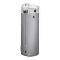
Specifies the model series covered by the manual.
Outlines the primary functions covered in the manual.
Covers upkeep, repairs, and warranty information.
Explains the purpose of the safety alert symbol.
Defines hazard levels indicated by safety symbols.
Lists general precautions before operating the appliance.
Details requirements for proper electrical grounding.
Warns about the hazard of hydrogen gas in water systems.
Details hazards related to flammable materials and gas.
Warns about carbon monoxide hazards and detector requirements.
Covers potential property damage from leaks or improper installation.
Warns about electrical hazards during installation and service.
Lists common abbreviations used throughout the manual.
Defines requirements for qualified installers and service agencies.
Describes the remote monitoring system's capabilities.
Explains connectivity to BACnet or Modbus systems.
Explains how the water heater's heat exchanger and burner work.
Describes the water heater's ability to modulate firing rate.
Details the components of the blower and burner assembly.
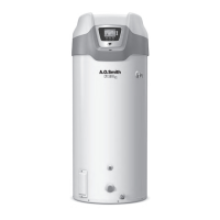
Identifies and describes all major components of the water heater.
Provides detailed descriptions of components visible from the sides.
Specifies required dimensions for installation space.
Details the required sizes for gas line connections.
Lists the storage capacities in gallons and liters.
Shows recovery capacities at various temperature rises.
Specifies required gas pressures for operation.
Lists the minimum supply gas line sizes for different models.
Warns about potential property damage from leaks.
Details required clearances from combustible materials.
Specifies required clearance for servicing the unit.
Outlines clearances for vent and intake air pipes.
Information on extending vent pipe lengths with different pipe sizes.
Details requirements for low and high pressure gas supply systems.
Specifies requirements for installing a supply gas regulator.
Covers power supply requirements and electrical grounding.
Emphasizes dedicated wiring and breakers for optimal performance.
Addresses potential issues with power supply quality.
Warns about severe burn risks from hot water.
Provides guidelines for connecting to dishwashing machines.
Explains closed systems and their implications.
Discusses thermal expansion and necessary precautions.
Highlights explosion risks related to the T&P valve.
Warns about water damage from improper discharge pipe installation.
Details specific requirements for the T&P discharge pipe.
Warns about burn hazard from hot water discharge.
Explains the built-in trap and its importance.
Discusses condensate pH and material compatibility for drain lines.
Warns about CO hazard from contaminated air.
Reinforces CO hazard warning and air intake needs.
Defines requirements for unconfined installation spaces.
Discusses air supply needs in tightly constructed buildings.
Defines confined spaces and air supply requirements.
Notes DV appliances are not factored into confined space calculations.
Addresses air replacement needs when exhaust fans are used.
Explains how to calculate opening sizes based on louvers/grilles.
Illustrates and describes two-opening air intake methods.
Illustrates and describes single-opening air intake methods.
Mandates CO detector installation per MA codes.
Specifies standards for approved CO detectors.
Requires specific signage for vent termination locations.
Outlines inspector's role in verifying MA requirements.
Lists exemptions from specific MA installation requirements.
Manufacturer's requirements for provided venting systems.
Manufacturer's requirements for systems not provided.
Reinforces CO hazard warning related to venting.
Provides general information on venting requirements.
Lists approved materials for vent and intake air piping.
Details equivalent lengths for field-supplied fittings.
Specifies types of primer and cement for pipe connections.
Outlines requirements for vent and intake air pipe sizes.
Specifies maximum allowed equivalent lengths for pipes.
Lists minimum equivalent lengths for vent pipes.
Details the maximum allowed number of elbows in vent piping.
Discusses factory-supplied fittings and their use.
Information on using a common horizontal direct vent kit.
Step-by-step instructions for power vent installations.
Step-by-step instructions for direct vent installations.
Details moisture drain requirements for DV intake air.
Specifies flat roof clearances for vertical terminations.
Instructions for direct vent vertical terminations.
Details sidewall termination installation for intake and vent pipes.
Specifies flat roof clearances for concentric terminations.
Instructions for vertical installation of 6-inch concentric kits.
Instructions for sidewall installation of 6-inch concentric kits.
Details clearance requirements for multiple concentric terminations.
Arrangement and clearance for four concentric terminations.
Arrangement and clearance for three concentric terminations.
Arrangements for multiple groups of concentric terminations.
Installation arrangements for two concentric terminations.
Installation arrangements for four concentric terminations.
Installation arrangements for eight concentric terminations.
Dimensions and specifications for low profile termination kits.
Diagram for Power Vent vertical venting configuration.
Diagram for Power Vent horizontal venting configuration.
Diagram for Direct Vent vertical venting configuration.
Diagram for Direct Vent horizontal venting configuration.
Diagram for DV with vertical vent and horizontal intake.
Diagram for DV with horizontal vent and vertical intake.
Diagram for DV vertical concentric venting.
Diagram for DV horizontal concentric venting.
Diagram for DV horizontal low profile venting.
Clearances for sidewall vent terminations in power vent configurations.
Clearances for sidewall vent terminations in direct vent configurations.
Instructions for installing the condensate drain.
Notes regarding condensate pH and drain line materials.
Details requirements for sizing gas supply lines.
Procedures for leak testing gas connections.
Instructions for purging gas lines.
General electrical wiring requirements.
Requirements for dedicated power wiring.
Details on connecting the power supply.
How to connect external controls to the enable/disable circuit.
References for water piping diagrams.
Warns of water damage from improper discharge pipe setup.
Details specific requirements for the T&P discharge pipe.
Details the high temperature limit control (ECO).
Explains thermostat control and scald hazard warnings.
Describes the modulation feature of the water heater.
Advice for high temperature applications.
Describes the default screen on the LCD touch display.
Explains how to navigate the control system menus.
Lists and describes status icons displayed on the unit.
Details the common operational states of the water heater.
Lists and describes the available control system menus.
Accesses settings for operating setpoint and differential.
Adjusts tank temperature differential for heating cycles.
Displays non-adjustable sensed tank temperature.
Calibrates temperature sensing and compensates for recirculation.
Displays current operating state of the water heater.
Allows selection of temperature units (°F or °C).
Adjusts LCD backlight illumination duration.
Adjusts the LCD screen contrast.
Total time the control system has been energized.
Total time the control system has been in heating state.
Total accumulated count of heating cycles.
Fault for restrictions in the exhaust pipe.
Lists past Fault and Alert messages with timestamps.
Running total of how many times each fault condition occurred.
Screen for entering customer contact information for alerts.
Essential checks and preparation before initial start-up.
Lists necessary test equipment for start-up.
Steps to prepare the water heater for initial start-up.
Safety warnings and instructions before lighting the appliance.
Step-by-step guide for operating the water heater.
Procedures for safely turning off gas supply.
How to determine the actual firing rate of the water heater.
Instructions to safely turn off the gas supply.
Safety warnings specific to high altitude installations.
CO hazard warning for high altitude installations.
Checklist for common installation errors and requirements.
Describes the step-by-step operational sequence.
Flow chart illustrating the sequence of operation.
Common operational problems due to installation errors.
Addresses issues with rough starts or operation.
Troubleshooting for momentary burner ignition.
Troubleshooting steps for insufficient hot water.
Procedures for resetting system lockouts.
General checks for diagnosing operational issues.
Warning about electrical shock during service.
Fault message for ignition failure.
Fault message for low gas pressure.
Fault message for blocked air intake.
Further causes and checks for blocked air intake.
Fault message for high temperature limit being exceeded.
Alert message indicating no water detected.
Schedule for routine maintenance tasks.
Instructions for draining and flushing the tank.
Warning about burn hazard during drain valve operation.
Instructions for removing sediment from the tank.
Procedures for removing lime scale deposits.
Using chemical solutions for lime scale removal.
Warning about burn hazard during T&P valve test.
Instructions for inspecting the vent system.
Diagram showing the layout of the Central Control Board.
Detailed wiring diagram of the water heater components.
Wiring diagram for storage tank or building recirculation.
Wiring diagram for dishwasher loop with toggle switch.
Piping diagram for single heater with building recirculation.
Piping diagram for two temp with high temp loop recirculation.
Piping diagram for single heater with vertical storage tank recirculation.
Piping diagram for single heater with horizontal storage tank recirculation.
Piping diagram for two heaters with building recirculation.
Piping diagram for three heaters with building recirculation.
Piping diagram for four heaters with building recirculation.
Defines the warranty period for tank and parts.
Details what is covered under the limited warranty.
Lists exclusions from the limited warranty coverage.
States the limitations and disclaimers of the warranty.
Provides information for service inquiries.
| Model | BTH 300 |
|---|---|
| Fuel Type | Natural Gas |
| Thermal Efficiency | 96% |
| Ignition Type | Electronic |
| Voltage | 120V |
| BTU Input | 300, 000 BTU/hr |