57
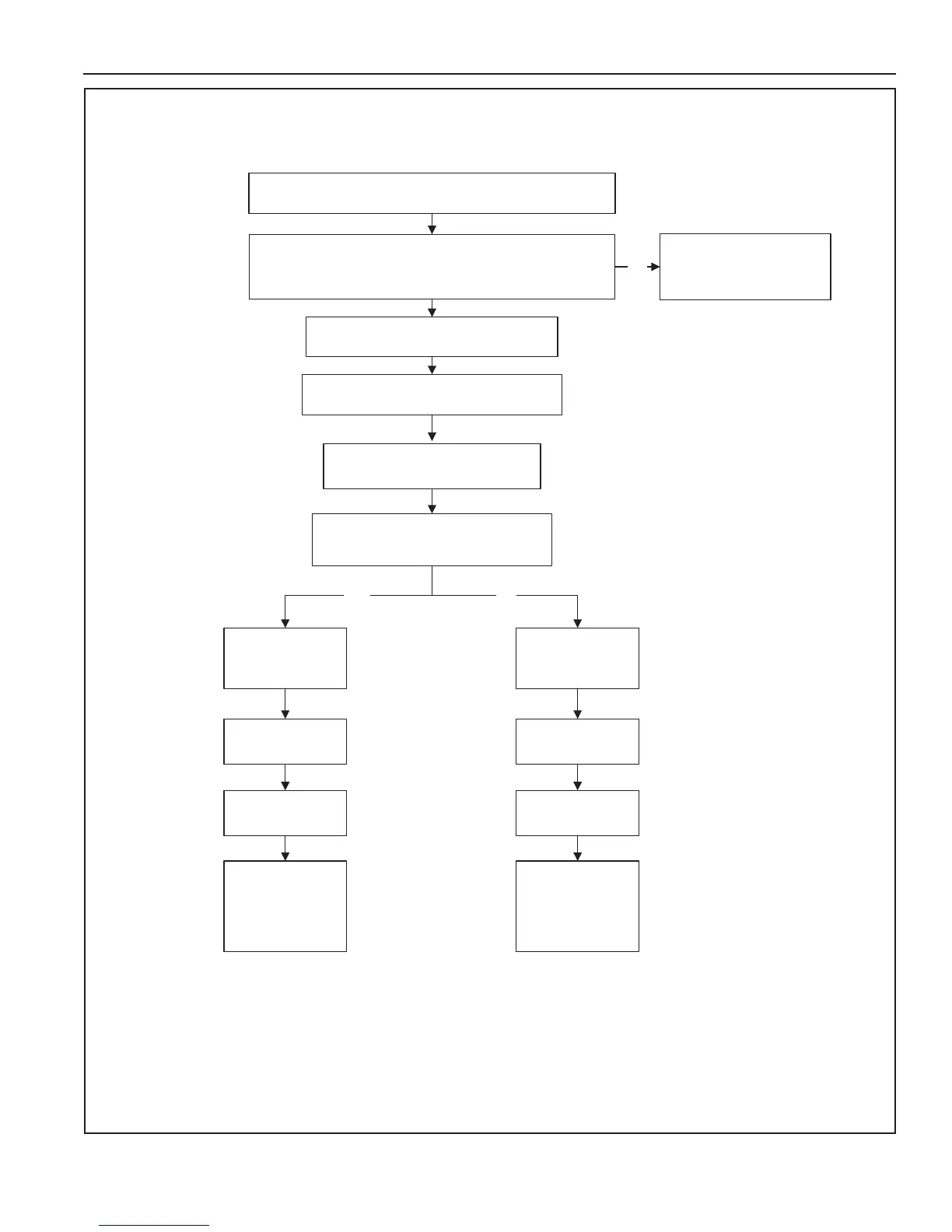
SEQUENCE OF OPERATION FLOW CHART
YES NO
Water is heated to
set point
24 VAC Gas Valve
de-energized
Inter-Purge cycle
24 VAC Gas Valve
de-energized
Retries up to
two more times
Post-Purge cycle
Control System
Locks Out
“Ignition Failure”
Fault Msg is
displayed
Water heater goes
into standby mode
If tank temperature drops below Operating Set Point minus
Differential setting a heating cycle is activated
Spark Ignition Control is energized.
24 VAC Gas Valve is energized
gas flows to Main Burner
Is flame sensed at the Main Burner ?
(control system monitors the flame sensor)
Control System Locks Out
Displays Fault Msg
NO
Combustion Blower is energized
Pre-Purge cycle
Control System performs diagnostic checks
Normal State of all pressure switches and ECO are checked
Pressure switches and ECO are verified closed
Sequence is shown with Enable/Disable Switch in the Enable position
Figure 54