START SWITCH REPLACEMENT AND ADJUSTMENT — 2-SPEED MOTORS
Proper starting switch adjustment on two-speed motors is essential for
satisfactory operation and contact life.
■ Disconnect all power to the motor before attempting any repair. Repair work
should only be performed by a qualified electric motor technician.
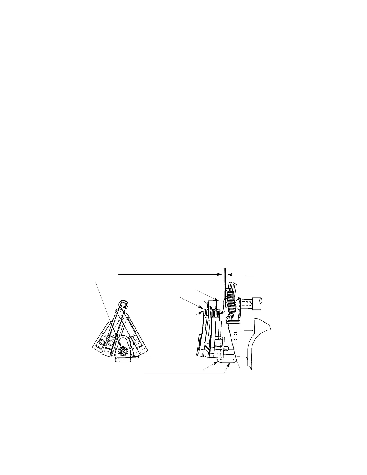
■ Fasten switch snugly to end bell, through “U” bracket with the switch mounting
screw provided.
■ A slight amount of switch movement is possible before the screw(s) is tightened.
C h e ck to see that the white switch button is centered over the governor projection.
■ Lift the governor weight (overcoming spring tension) until it touches the stops
on the governor. Clearance between the governor projection and white button
should be .010” to .040”.
■ Most newer models use only one screw to secure and adjust the switch. When a
new switch is installed, or an existing switch is being reinstalled, the "U" bracket
should be opened slightly to insure sufficient tension against the screw. Tighten
only when adjusting. If the screw is loosened, it should be removed and the "U"
bracket should again be opened slightly.
■ Under no circumstances should switch contact leafs be bent or deformed in an
attempt to obtain proper contact clearance.
■ Once the governor weight is released, and the governor projection pushes on the
switch button, contact Z should move away from the motor by approximately
.030”. This movement assures that the points will have sufficient contact no
matter what position the rotor/shaft and governor projection are in at rest.
In run position contacts X & Y must be open and contact Z closed. At rest,
contacts X & Y must be closed and contact Z open.
Pump Motors 41
Level 2 A.O.Smith
SWITCH ADJUSTMENT
SWITCH ADJUSTING SCREW
—TIGHTEN ONLY TO OBTAIN
PROPER CLEARANCE—
WHITE SWITCH BUTTON
X
Z
Y
SWITCH ASSEMBLY
SWITCH MOUNTING “U” BRACKET
GOVERNOR ASSEMBLY SHOWN
IN OPEN POSITION
CLEARANCE WHEN
ACTUATOR IS IN
RUN POSITION AS
SHOWN
.010
.040
START CONTACTS
REMOVE AND OPEN "U" BRACKET SLIGHTLY TO INSURE
SUFFICIENT SCREW TENSION WHEN INSTALLING NEW
SWITCH OR AFTER SCREW HAS BEEN LOOSENED.