VF BOILER SERVICE MANUAL
AOS WPC - Tech Training 28 of 72 Ashland City, TN © 2007
Servicing should only be performed by a Qualified Service Agent
MCB - SECTION B
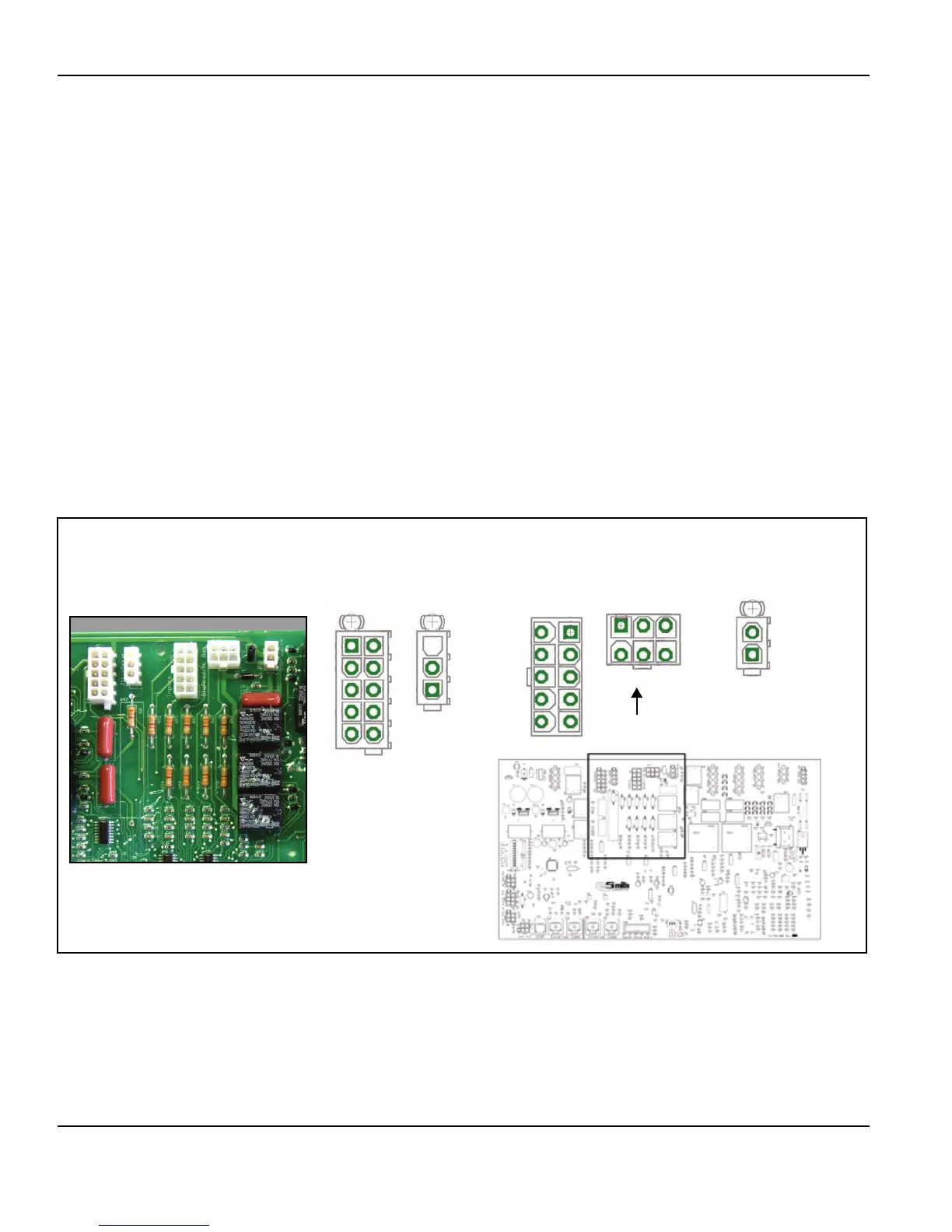
The upper middle section of the MCB contains the following sockets/components:
†
J4 Socket (Outputs/Inputs)
• Pin 1 - Spare - not used
• Pin 2 - Spare - not used
• Pin 3 - Spare - not used
• Pin 4 - 24 VAC line low water cut off (optional)
• Pin 5 - Low water cut off proving signal
• Pin 6 - 24 VAC line low water cut off (optional)
• Pin 7 - 24 VAC line alarm bell circuit (optional)
• Pin 8 - 24 VAC line alarm bell circuit (optional)
• Pin 9 - Spare - not used
• Pin 10 - Spare - not used
J11 Socket (Enable/Disable or Tstat circuit)
• Pin 1 - 24 VAC to dry control contacts
• Pin 2 - 24 VAC to dry control contacts
• Pin 3 - Spare - not used
J19 Socket
• Pin 1 - 24 VAC - Gas valve solenoid
• Pin 2 - 24 VAC - Gas valve solenoid
†. J4 Socket Pins 1-8 provide 24 VAC circuits for optional components and equipment. These are switched
24 VAC control circuits with a maximum amp rating of 1 amp. When these optional components are used the
MCB must be configured to recognize and enable the components by setting the SW1 dip switches
accordingly. See page 30.
B
2
1
1
2
3
4
5
6
7
8
9
10
1
2
3
4
5
3
2
1
6
7
8
9
10
1 2 3
4 5 6
J4 Outputs
J11 Tstat J5 Inputs
J17 BlwPrv/Hi Gas
J19 Gas Valve
The MCB circuit board is mounted upside down on VF boilers compared to the illustrations below.
J5 Socket (Inputs)
• Pin 1 - 24 VAC Flow switch
• Pin 2 - 24 VAC Flow switch
• Pin 3 - 24 VAC Low gas press switch
• Pin 4 - 24 VAC Low gas press switch
• Pin 5 - 24 VAC Blocked flue (exhaust) switch
• Pin 6 - 24 VAC Blocked flue (exhaust) switch
• Pin 7 - 24 VAC IRI prover switch - N/A on VF boilers
• Pin 8 - 24 VAC IRI prover switch - N/A on VF boilers
• Pin 9 - Spare - Not used
• Pin 10 - Spare - Not used
J17 Socket (Blower Prover / Hi Gas Press Switch)
• Pin 1 - 24 VAC High Blower Prover switch
• Pin 2 - 24 VAC High Blower Prover switch
• Pin 3 - 24 VAC High gas press switch (optional)
• Pin 4 - 24 VAC High gas press switch (optional)
• Pin 5 - 24 VAC Low Blower Prover switch
• Pin 6 - 24 VAC Low Blower Prover switch
 Loading...