13
4 ELECTRICAL INSTALLATION
White
Red
Black
Screen
Core
Green
To Intrinsically
Safe pH Transmitter
To In-Line/Flow/Dip
pH System
Grey
Blue
Green
Red
White
Measuring
Electrode
(Inner Core)
Screen
Fly Lead
Ref
Temp.
Comp.
Solution
Earth
(For use with 4530/4540 and 9180 transmitters.
For other transmitters the Solution Earth termination
can be removed)
Black
elbaCmetsyS0354535404545454
gnirusaeM
edortcelE
)xaocforenni(
42422222
ecnerefeR
)kcalb(
62624242
.pmoC.pmeT
)der(
11 9292
.pmoC.pmeT
)etihw(
22 0303
.pmoC.pmeT
)der(
33 1313
htraEnoituloS
)htrae(
52A/N32A/N
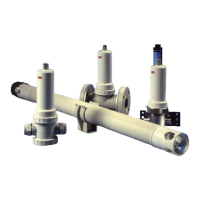
4.1 Connection to AX, 4500 and 4600 Series Transmitters – Fig. 4.1 and Table 4.1
System cable connections to the pH meter are shown in Fig. 4.1. For AX and 4600 series transmitters refer to the pH meter instruction
manual. For 4500 Series transmitters refer to the list of equivalent connections shown in Table 4.1.
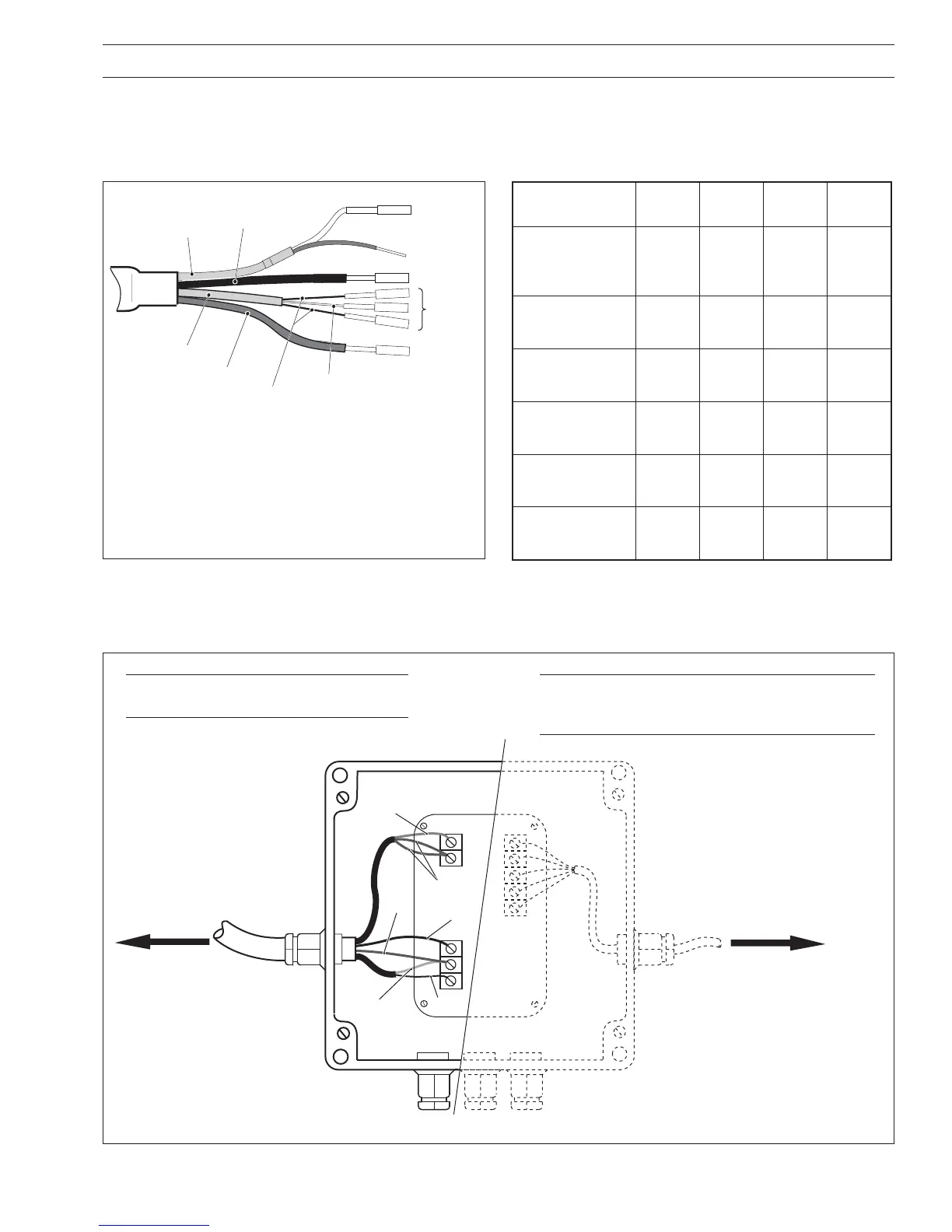
4.2 Connection to Hazardous Area Systems – Figs. 4.1 and 4.2
Connect the electrode terminals to the junction box supplied – see Fig. 4.2.
Fig. 4.1 System Connections
Table 4.1 Series 4500 Connection Equivalents
Fig. 4.2 Junction Box Electrode Connections
Note. Connect together the two red
leads from the temperature compensator.
Note. Follow the instructions in the intrinsically
safe pH measuring system manual for the
remainder of the electrical installation.