Do you have a question about the ABB MagMaster and is the answer not in the manual?
Crucial safety and installation warnings for MagMaster Approved/Hazardous Versions.
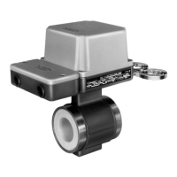
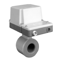
Detailed instructions for the physical installation and mounting of the flowmeter transmitter and sensor.
Essential procedures for grounding the flowmeter system for safety and signal integrity.
Guidelines for ensuring proper connection between the transmitter and sensor.
Important cautions for handling and connecting remote sensor cables.
Instructions for connecting the transmitter unit, including terminal identification.
Overview of various input and output signal connections for the flowmeter.
Details on standard and dual current output configurations, including HART connections.
Guides for connecting AC and DC power supplies to the flowmeter transmitter.
Critical warnings regarding power supply disconnection and electrical installation standards.
Essential safety warnings for plant safety and serial link isolation during operation.
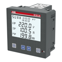
Step-by-step guide to powering on and starting up the flowmeter system.
Specifications for various output types (mA, pulse) and input types (contact, logic).
| Type | Magnetic Flow Meter |
|---|---|
| Process connection | Wafer, Flanged |
| Lining material | PTFE, hard rubber |
| Electrode material | Stainless Steel, Hastelloy C, Tantalum, Platinum |
| Fluid temperature | Up to 180 °C (356 °F) depending on liner |
| Communication | HART, FOUNDATION Fieldbus, PROFIBUS PA |
| Approvals | ATEX, IECEx, FM, CSA, SIL |
| Diagnostics | empty pipe detection |
| Output Signal | 4-20 mA, pulse, frequency |
| Power Supply | 100 to 240 V AC, 24 V AC/DC |
| Process Temperature Range | -40°C to +180°C (depending on lining material) |
| Ambient Temperature Range | -40°C to +60°C |
| Protection Class | IP67, IP68 |
| Material | Carbon steel, stainless steel |
| Flow Rate Range | 0.03 to 12 m/s (0.1 to 39 ft/s) |