12
CD1
CD2
GROUND
White
Violet
Ground Wire
Sensor Cable
Adaptor Plug
Yellow
Red
Blue
Pink
Grey
SIG GND
DS 1
SIG 1
SIG 2
DS 2
…3 ELECTRICAL INSTALLATION
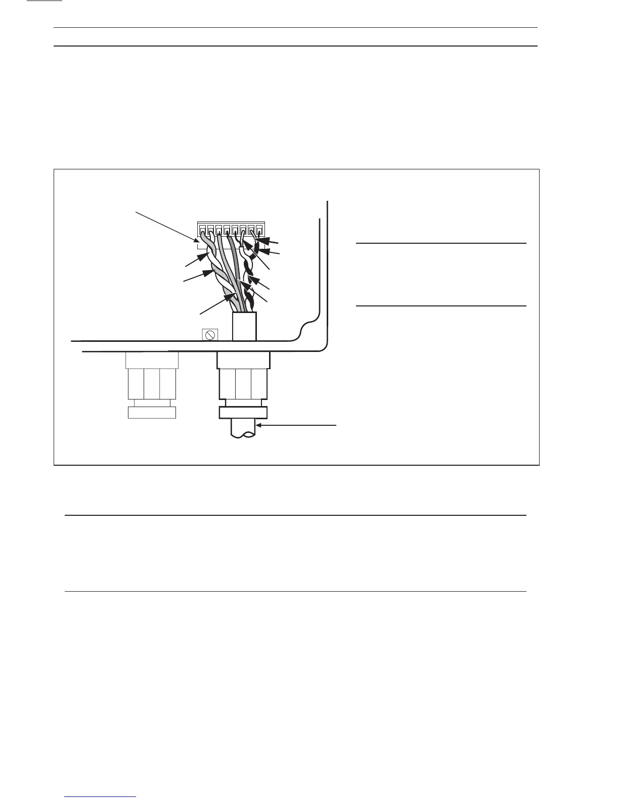
3.3.3 Alternate Wiring Configuration
Some later transmitters have an alternative (plug-and-socket) sensor wiring configuration (see Fig. 3.15)
This connector may be either an integral part of the termination area or, alternatively, part of the CalMaster
adapter board. The wiring of both these variants is the same.
To wire the adaptor plug, carefully pull off the plug from the adaptor board, connect the wires (using a
screwdriver with a 2.5mm blade to tighten the terminal screws) and replace the plug.
3.4 Input/Output Connections
Caution.
• Refer to SPECIFICATION for Input/Output ratings.
• Inductive loads must be suppressed or clamped to limit voltage swings
• Capacitive loads must be inrush current limited.
• Hazardous area requirements are not considered in the following pages.
Fig 3.15 Fitting the Sensor Wiring onto the Adaptor
Caution. Remove any exposed
black conductive layer from the
inner insulation of both coaxial
cables.