3 ELECTRICAL INSTALLATION…
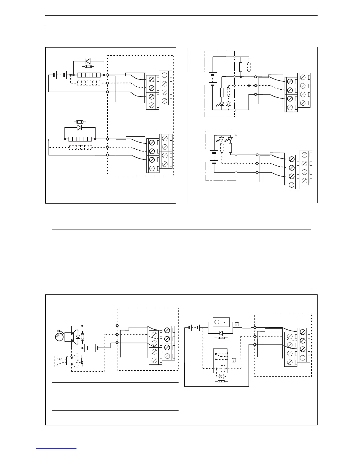
Fig. 3.16 Frequency Output Connections
Fig. 3.18 PLC Interface
Fig. 3.17 Alarm Output Connections
Information. Relay and Timer Switch
shown for example only. Connect as
required.
3.4.1 Frequency Outputs – Fig. 3.16 3.4.3 PLC Interface – Fig. 3.18
3.4.2 Alarm Outputs – Fig. 3.17
Information.
• Inductive loads may be suppressed by diodes (D) – 1N4004 or similar.
• Inrush currents are limited to 1 Amp by resistor R – e.g. 27 1W for 24V systems.
• Operation of outputs is programmable – see Configuration Manual for details.
• Frequency and Alarm outputs share a common return with contact input.
• External isolators not normally required, as the pulse, alarm and contact circuits are
electrically separated from all other Magmaster connections.