ALARM 1
ALARM 2
PLS 0V
EXT I/P+
F OUT A
F OUT B
PLS 0V
EXT I/P-
ALARM 1
ALARM 2
PLS 0V
EXT I/P+
F OUT A
F OUT B
PLS 0V
EXT I/P-
…3 ELECTRICAL INSTALLATION
3.3.2 Transmitters (All versions)
Caution.
• Remove any exposed black conductive layer from the inner insulation of both coaxial cables.
• Substitute sensor cable of any kind is not acceptable.
• Do not make connections except as shown.
• Twist cable pairs together as shown.
• Sleeve ALL bare wires.
• Sensor cable may only be joined using company supplied junction box - available
separately.
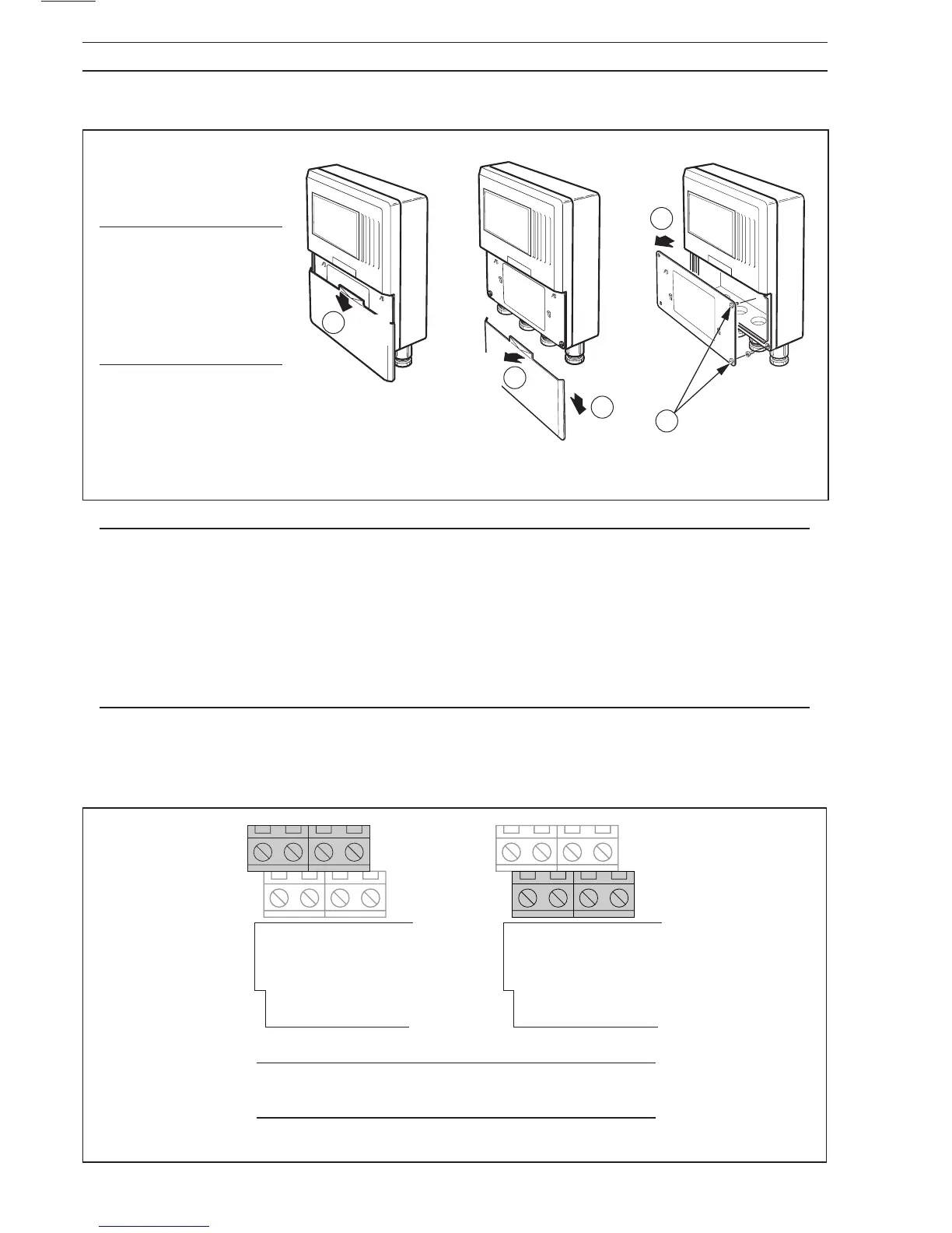
Terminal Identification
Each terminal block has two parallel rows of connectors. The corresponding label for each connector is
printed on the board as shown in fig 3.12.
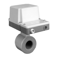
Caution. Unused
cable entries must
be blanked with the
permanent blanking
plugs supplied with
the transmitters.
Fig. 3.11 Transmitter Connection Terminal
Caution. It is important that all wires are correctly
connected to their corresponding terminal.
Fig 3.12 Terminal Identification