9
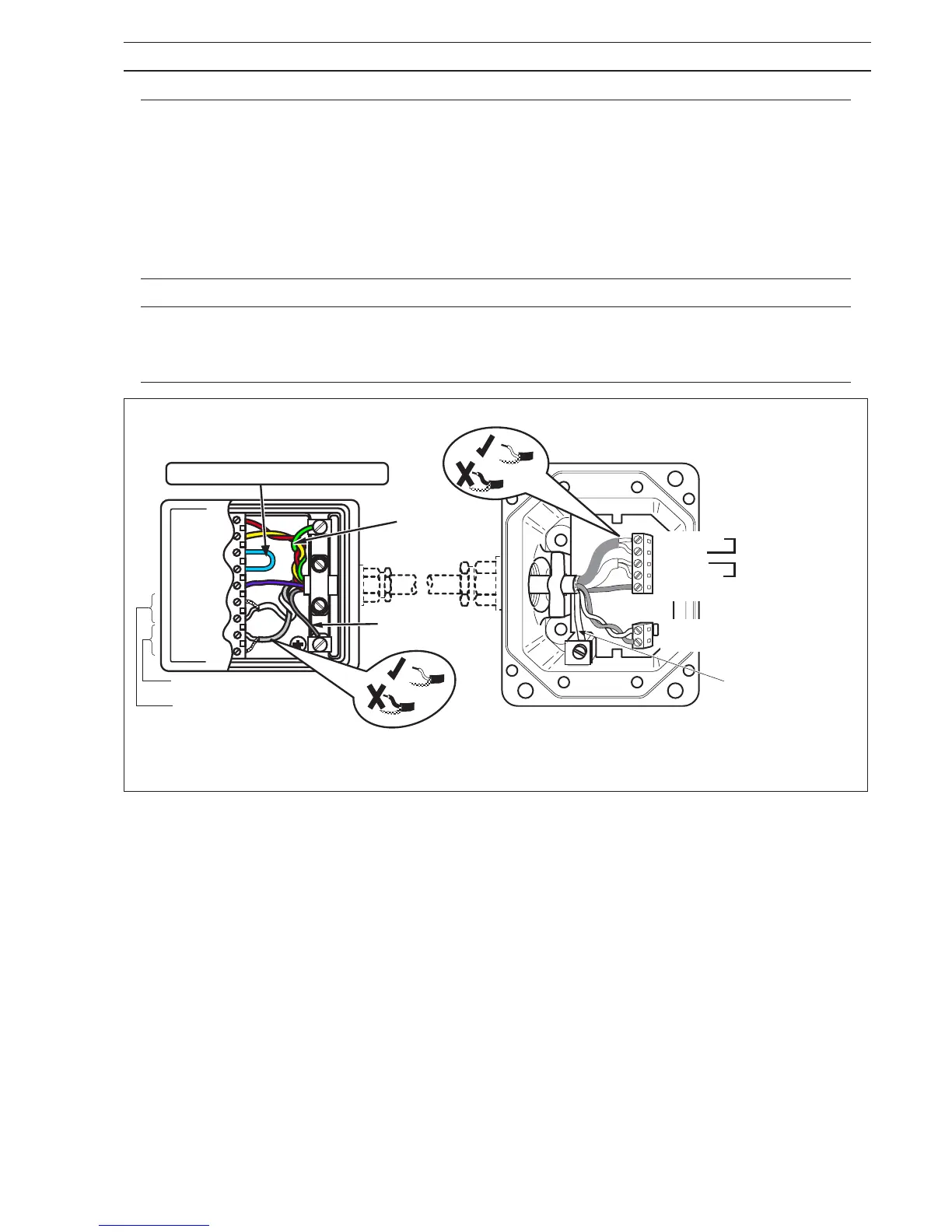
Note. If link is fitted, do NOT remove
CD1
CD2
SIG GND
DS1
SIG1
SIG2
DS2
Red
Yellow
Screen
Pink
Blue
Screen
Violet
White Coaxial
Sleeved Ground
Wire
Grey Coaxial
Yellow/Green
(if present)
––7 Screen
––6 Pink
––5 Blue
––4 Screen
––3 Violet
––2 Yellow
––1 Red
White
coaxial
Grey
coaxial
1
3
2
7
Alternative Terminal Box Standard Terminal Box
Sleeved Ground Wire
and Yellow/Green
(if present)
3 ELECTRICAL INSTALLATION…
Caution. (Remote versions)
• Remove any exposed black conductive layer from under coaxial screens.
• Make connections only as shown.
• Sleeve all bare wiring.
• Twist RED and YELLOW cores lightly together.
• Twist WHITE and GREY coaxial cables lightly together.
• Maintain Environmental Protection at all times.
• Conduit connections must provide cable entry sealing.
Information. (Remote versions)
• Refer to ENVIRONMENTAL PROTECTION (Appendix A).
• Internal appearance of Terminal Box may vary from that shown.
Fig. 3.10 Sensor Terminal Box Connections (Remote version)